Nissan Maxima Service and Repair Manual: Door mirror motor
Description
It makes mirror face operate from side to side and up and down with the electric power that automatic drive positioner control unit supplies.
Component Function Chec
1. CHECK DOOR MIRROR MOTOR FUNCTION
Check the operation with "MIRROR MOTOR RH" and "MIRROR MOTOR LH" in "ACTIVE TEST" mode with CONSULT.
Diagnosis Procedure
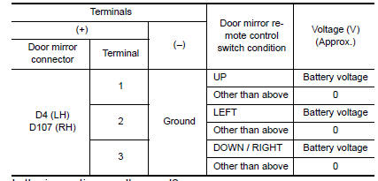
1. CHECK DOOR MIRROR MOTOR INPUT SIGNAL
- Turn ignition switch ON.
- Check voltage between door mirror connector and ground.
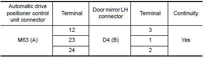
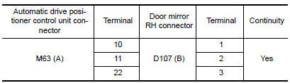
2. CHECK HARNESS CONTINUITY
- Turn ignition switch OFF.
- Disconnect automatic drive positioner control unit and door mirror.
- Check continuity between automatic drive positioner control unit connector and door mirror connector.
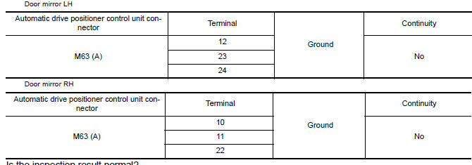
Door mirror LH
Door mirror RH
- Check continuity between automatic drive positioner control unit connector and ground.
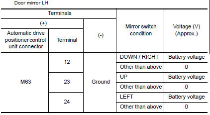
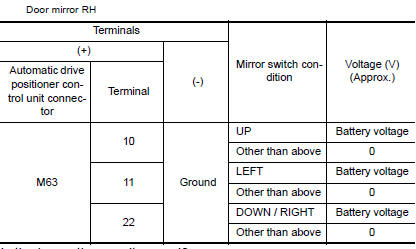
3. CHECK AUTOMATIC DRIVE POSITIONER CONTROL UNIT OUTPUT SIGNAL
- Connect automatic drive positioner control unit.
- Turn ignition switch ON.
- Check voltage between automatic drive positioner control unit connector and ground.
4. CHECK DOOR MIRROR MOTOR
Check door mirror motor.
Component Inspection
1. CHECK DOOR MIRROR MOTOR-I
Check that door mirror motor does not trap foreign objects and does not have any damage.
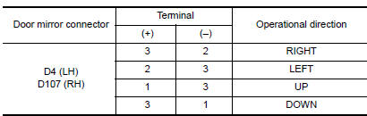
2. CHECK DOOR MIRROR MOTOR-II
- Turn ignition switch OFF.
- Disconnect door mirror.
- Apply 12V to each power supply terminal of door mirror motor.
 Telescopic motor
Description
The telescopic motor is installed to the steering column assembly.
The telescopic motor is activated with the automatic drive
positioner control unit.
Compresses the steering co ...
 Seat memory indicator lamp
Description
Memory switch is equipped on the seat memory switch installed to the
driver side door trim. The operation signal is input to the driver seat
control unit when the memory switch i ...
Other materials:
U1000 CAN comm circuit
Description
CAN (Controller Area Network) is a serial communication
line for real time applications. It is an on-vehicle multiplex
communication line with high data communication speed and excellent error
detection ability. Modern
vehicle is equipped with many electronic control unit, and e ...
P0172, P0175 fuel injection system function
DTC Logic
DTC DETECTION LOGIC
With the Air/Fuel Mixture Ratio Self-Learning Control, the actual mixture
ratio can be brought closely to the
theoretical mixture ratio based on the mixture ratio feedback signal from A/F
sensor 1. The ECM calculates
the necessary compensation to correct the o ...
P1722 vehicle speed
Description
The vehicle speed signal is transmitted from ABS actuator
and electric unit (control unit) to TCM via CAN communication
line.
DTC Logic
DTC DETECTION LOGIC
DTC CONFIRMATION PROCEDURE
CAUTION:
Always drive vehicle at a safe speed.
NOTE:
Immediately after performing any "DT ...
Nissan Maxima Owners Manual
- Illustrated table of contents
- Safety-Seats, seat belts and supplemental restraint system
- Instruments and controls
- Pre-driving checks and adjustments
- Monitor, climate, audio, phone and voice recognition systems
- Starting and driving
- In case of emergency
- Appearance and care
- Do-it-yourself
- Maintenance and schedules
- Technical and consumer information
Nissan Maxima Service and Repair Manual

0.006