Nissan Maxima Service and Repair Manual: Seat memory indicator lamp
Description
- Memory switch is equipped on the seat memory switch installed to the driver side door trim. The operation signal is input to the driver seat control unit when the memory switch is operated.
- The status of automatic drive positioner system can be checked according to the illuminating/flashing status.
Component Function Check
1. CHECK FUNCTION
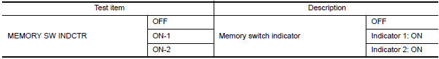
- Select "MEMORY SW INDCTR" in "ACTIVE TEST" mode with CONSULT.
- Check the memory indicator operation.
Diagnosis Procedure
1. CHECK SEAT MEMORY INDICATOR CIRCUIT
- Turn ignition switch OFF.
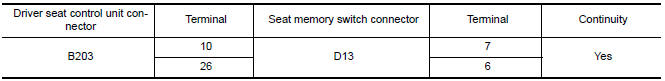
- Disconnect driver seat control unit and seat memory switch.
- Check continuity between driver seat control unit harness connector and seat memory switch harness connector.
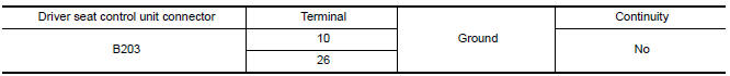
- Check continuity between driver seat control unit harness connector and ground.
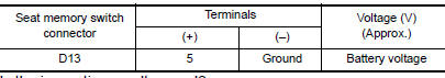
2. CHECK MEMORY INDICATOR POWER SUPPLY
Check voltage between seat memory switch harness connector and ground.
3. CHECK MEMORY INDICATOR
4. CHECK INTERMITTENT INCIDENT
Component Inspection
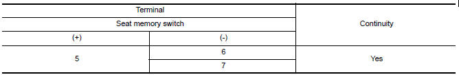
1. CHECK SEAT MEMORY INDICATOR
- Disconnect seat memory switch.
- Check continuity between seat memory switch terminals.
 Door mirror motor
Description
It makes mirror face operate from side to side and up and down with the
electric power that automatic drive positioner control unit supplies.
Component Function Chec
1. CHECK DOOR MIR ...

Other materials:
Diagnosis system (BCM)
COMMON ITEM
COMMON ITEM : CONSULT Function (BCM - COMMON ITEM)
APPLICATION ITEM
CONSULT performs the following functions via CAN communication with BCM.
SYSTEM APPLICATION
BCM can perform the following functions.
HEADLAMP
HEADLAMP : CONSULT Function (BCM - HEAD LAMP)
DATA MONITOR
ACTI ...
Outside key antenna
REAR BUMPER
REAR BUMPER : Removal and Installation
REMOVAL
Remove the rear bumper. Refer to EXT-17, "Removal and
Installation".
Disconnect harness connector (1) from the outside key antenna
(rear bumper) (2).
Remove the outside key antenna (rear bumper) screws (A) and
...
Seat belt extenders
If, because of body size or driving position, it is
not possible to properly fit the lap/shoulder belt
and fasten it, an extender that is compatible with
the installed seat belts is available for purchase.
The extender adds approximately 8 in (200 mm)
of length and may be used for either the ...
Nissan Maxima Owners Manual
- Illustrated table of contents
- Safety-Seats, seat belts and supplemental restraint system
- Instruments and controls
- Pre-driving checks and adjustments
- Monitor, climate, audio, phone and voice recognition systems
- Starting and driving
- In case of emergency
- Appearance and care
- Do-it-yourself
- Maintenance and schedules
- Technical and consumer information
Nissan Maxima Service and Repair Manual

0.0053