Nissan Maxima Service and Repair Manual: Diagnosis system (bluetooth control unit)
Diagnosis Description
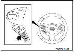
The Bluetooth control unit has two diagnostic checks. The first diagnostic check is performed automatically every ignition cycle during control unit initialization. The second diagnostic check is performed by the technician using the steering wheel audio control switches prior to trouble diagnosis.
BLUETOOTH CONTROL UNIT INITIALIZATION CHECKS
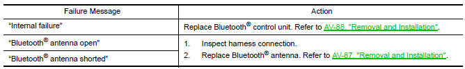
- Internal control unit failure
- Bluetooth antenna connection open or shorted
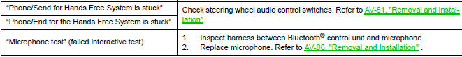
- Steering wheel audio control switches [
 (PHONE/SEND),
  (PHONE/END)]
stuck closed
(PHONE/END)]
stuck closed - Vehicle speed pulse count
- Microphone connection test (with playback to operator)
- Bluetooth inquiry check
OPERATION PROCEDURE
- Turn ignition switch to ACC or ON.
- Wait for the Bluetooth system to complete initialization. This may take up to 10 seconds.
- Press and hold the steering wheel audio control switch
 (PHONE/SEND) button for at least 5
seconds. The Bluetooth system will begin to play a verbal prompt.
(PHONE/SEND) button for at least 5
seconds. The Bluetooth system will begin to play a verbal prompt.
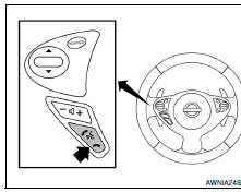
- While the prompt is playing, press and hold the steering wheel audio
control switch
 (PHONE/END) button until you
hear the "Diagnostics mode" prompt. The Bluetooth system will sound a
5-second beep.
(PHONE/END) button until you
hear the "Diagnostics mode" prompt. The Bluetooth system will sound a
5-second beep. - While the beep is sounding, press and hold the steering wheel
audio control switch
 (PHONE/END) button again
until you hear prompts.
(PHONE/END) button again
until you hear prompts. - The Bluetooth system has now entered into the diagnostic mode. Results of the diagnostic checks will be verbalized to the technician. Refer to AV-25, "Work Flow".
- After the failure records are reported, an interactive microphone test will be performed. Follow the voice prompt. If the microphone test fails, refer to AV-25, "Work Flow".
- Self-diagnosis mode is complete when the voice prompt says "All diagnostic functions completed".
Work Flow
 Diagnosis system (audio unit)
Diagnosis Description
Self-diagnosis mode can perform the following items.
Versions display
Channel check diagnosis
Key check diagnosis
AV communication diagnosis
VERSIONS DISPLAY FUNCTI ...

Other materials:
Symptom diagnosis
ADP SYSTEM SYMPTOMS
Symptom Table
SYMPTOM 1
SYMPTOM 2
SYMPTOM 3
SYMPTOM 4
SYMPTOM 5
NORMAL OPERATING CONDITION
Description
The following symptoms are normal operations, and they do not indicate a
malfunction.
...
Inspection and adjustment
REAR VIEW MONITOR POSSIBLE ROUTE LINE CENTER POSITION ADJUSTMENT
REAR VIEW MONITOR POSSIBLE ROUTE LINE CENTER POSITION ADJUSTMENT :
Description
Adjust the center position of the possible route line of the rear view
monitor if it is shifted.
REAR VIEW MONITOR POSSIBLE ROUTE LINE CENTER POSITIO ...
AV control unit
Reference Value
VALUES ON THE DIAGNOSIS TOOL
CONSULT data monitor item
TERMINAL LAYOUT
PHYSICAL VALUES
*1 With satellite radio
DTC Index
Self-diagnosis results display item
...
Nissan Maxima Owners Manual
- Illustrated table of contents
- Safety-Seats, seat belts and supplemental restraint system
- Instruments and controls
- Pre-driving checks and adjustments
- Monitor, climate, audio, phone and voice recognition systems
- Starting and driving
- In case of emergency
- Appearance and care
- Do-it-yourself
- Maintenance and schedules
- Technical and consumer information
Nissan Maxima Service and Repair Manual

0.0074