Nissan Maxima Service and Repair Manual: Signal buffer system
System Diagram
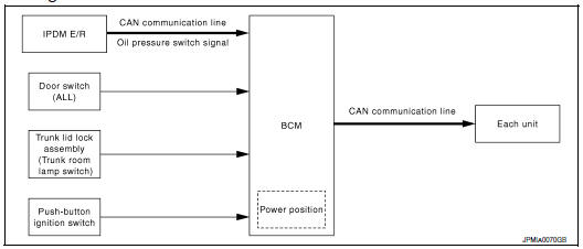
System Description
OUTLINE
BCM has the signal transmission function that outputs/transmits each input/received signal to each unit.
Signal transmission function list
|
Signal name |
Input |
Output |
Description |
|
Engine switch (push switch) | IPDM E/R (CAN) | Inputs the push-button ignition switch (push switch) signal and transmits the ignition switch status judged with BCM via CAN communication |
| Door switch signal | Any door switch |
|
Inputs the door switch signal and transmits it via CAN communication |
| Trunk switch signal | Trunk room lamp switch | Combination meter (CAN) | Inputs the trunk room lamp switch signal and transmits the trunk switch signal via CAN communication |
| Oil pressure switch signal | IPDM E/R (CAN) | Combination meter (CAN) | Transmits the received oil pressure switch signal via CAN communication |
 Combination switch reading system
System Diagram
System Description
OUTLINE
BCM reads the status of the combination switch (light, turn
signal, wiper and washer) and recognizes the
status of each switch.
BCM has a co ...
 Power consumption control system
System Diagram
System Description
OUTLINE
BCM incorporates a power saving control function that reduces the
power consumption according to the
vehicle status.
BCM switches the status ...
Other materials:
P0127 IAT sensor
Description
The intake air temperature sensor is built-into the mass air flow sensor
(1). The sensor detects intake air temperature and transmits a
signal to the ECM.
The temperature sensing unit uses a thermistor which is sensitive to
the change in temperature. Electrical resistance o ...
Diagnosis system (BCM)
COMMON ITEM
COMMON ITEM : CONSULT Function (BCM - COMMON ITE
APPLICATION ITEM
CONSULT performs the following functions via CAN communication with BC
SYSTEM APPLICATION
BCM can perform the following functions.
INT LAMP
INT LAMP : CONSULT Function (BCM - INT LAMP)
DATA MONITOR
ACTIVE TE ...
Child safety
WARNING
Do not allow children to play with the seat
belts. Most seating positions are
equipped with Automatic Locking Retractor
(ALR) mode seat belts. If the seat belt
becomes wrapped around a child's neck
with the ALR mode activated, the child can
be seriously injured or killed if the seat
...
Nissan Maxima Owners Manual
- Illustrated table of contents
- Safety-Seats, seat belts and supplemental restraint system
- Instruments and controls
- Pre-driving checks and adjustments
- Monitor, climate, audio, phone and voice recognition systems
- Starting and driving
- In case of emergency
- Appearance and care
- Do-it-yourself
- Maintenance and schedules
- Technical and consumer information
Nissan Maxima Service and Repair Manual

0.0088