
Nissan Maxima Service and Repair Manual: Rear view monitor system
System Diagram
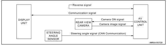
System Description
When the shift selector is in the R position, the display shows a view to the rear of the vehicle. Lines which indicate the vehicle clearance and distances are also displayed.
Component Parts Location
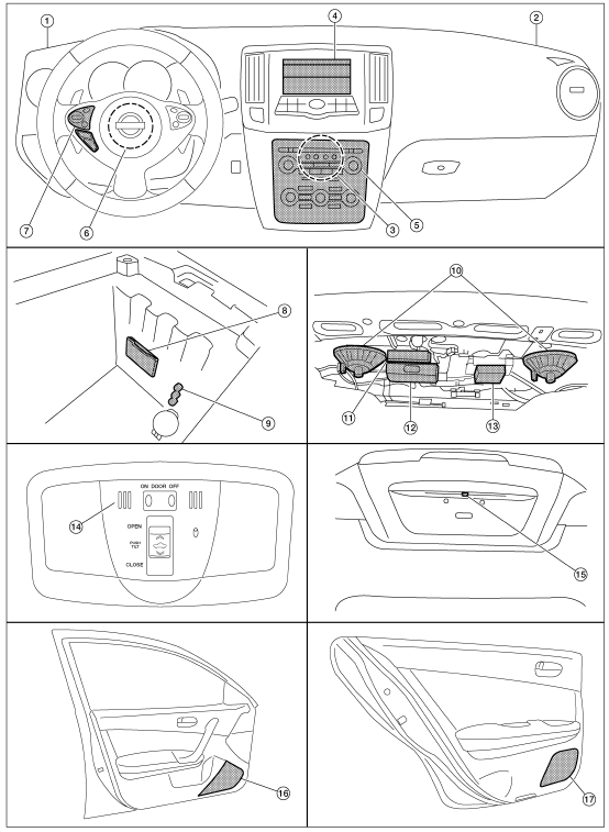
- Tweeter LH M143
- Tweeter RH M144
- AV control unit M115, M116, M117, M118, M119, M120, M121 (located behind A/C and AV switch assembly)
- Display unit M141
- A/C and AV switch assembly M98
- Steering angle sensor M53 [located in steering column behind combination switch (spiral cable)]
- Steering wheel audio control switches
- USB interface M211 (view in center console)
- Aux jack M209
- Subwoofer (view under rear parcel shelf) LH B16 RH B17
- Satellite radio tuner B111
- Bluetooth control unit B125, B130, B131
- Subwoofer amp. B21
- Microphone R7
- Rear view camera T101
- Front door speaker LH D3 RH D103
- Rear door speaker LH D202 RH D302
Component Description
| Part name | Description |
| AV control unit |
|
| Rear view camera |
|
| Steering angle sensor | Sends steering angle information to the AV control unit via CAN communication |
 Audio system
System Diagram
System Description
AUDIO SYSTEM
The audio system consists of the following components
AV control unit
Display unit
Window antenna
Steering wheel audio control switches
...
 Hands-free phone system
System Diagram
System Description
Refer to the Owner's Manual for Bluetooth telephone system operating
instructions.
NOTE: Cellular telephones must have their wireless
connection set up (pair ...
Other materials:
Intake sensor
Removal and Installation
REMOVAL
Remove the evaporator (2). Refer to HA-48, "EVAPORATOR:
Removal and Installation".
Release the intake sensor clip (A), then remove the intake sensor
(1).
CAUTION:
Mark the mounting position of the intake sensor.
Do not damage the evapora ...
Cooling system
Cooling Circuit
Cylinder block (RH)
Oil cooler
Cylinder head (RH)
Water pump
Radiator
Water inlet
Thermostat
Cylinder head (LH)
Cylinder block (LH)
To heater
To electric throttle control actuator
From heater
From electric throttle control act ...
Audio unit
Reference Value
TERMINAL LAYOUT
PHYSICAL VALUES
...
Nissan Maxima Owners Manual
- Illustrated table of contents
- Safety-Seats, seat belts and supplemental restraint system
- Instruments and controls
- Pre-driving checks and adjustments
- Monitor, climate, audio, phone and voice recognition systems
- Starting and driving
- In case of emergency
- Appearance and care
- Do-it-yourself
- Maintenance and schedules
- Technical and consumer information
Nissan Maxima Service and Repair Manual

0.0101