Nissan Maxima Service and Repair Manual: Power consumption control system
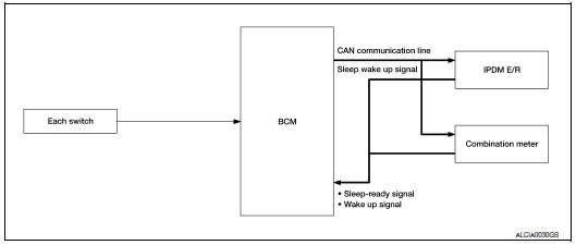
System Diagram
System Description
OUTLINE
- BCM incorporates a power saving control function that reduces the power consumption according to the vehicle status.
- BCM switches the status (control mode) by itself with the power saving control function. It performs the sleep request to each unit (IPDM E/R and combination meter) that operates with the ignition switch OFF.
Normal mode (wake-up)
- CAN communication is normally performed with other units
- Each control with BCM is operating properly
CAN communication sleep mode (CAN sleep)
- CAN transmission is stopped
- Control with BCM only is operating
Low power consumption mode (BCM sleep)
- Low power consumption control is active
- CAN transmission is stopped
LOW POWER CONSUMPTION CONTROL WITH BCM
BCM reduces the power consumption with the following operation in the low power consumption mode.
- The reading interval of the each switches changes from 10 ms interval to 60 ms interval.
Sleep mode activation
- BCM receives the sleep-ready signal (ready) from IPDM E/R and combination meter via CAN communication.
- BCM transmits the sleep wake up signal (sleep) to each unit when all of the CAN sleep conditions are fulfilled.
- Each unit stops the transmission of CAN communication with the sleep wakeup signal. BCM is in CAN communication sleep mode.
- BCM is in the low power consumption mode and perform the low power consumption control when all of the
BCM sleep conditions are fulfilled with CAN sleep condition.
Sleep condition
|
CAN sleep condition |
BCM sleep condition |
|
|
Wake-up operation
- BCM changes from the low power consumption mode to the CAN communication sleep mode when any of the BCM wake-up conditions is fulfilled. Only the control with BCM is activated.
- BCM transmits the sleep wake up signal (wake up) to each unit when any of the CAN wake-up conditions is fulfilled. It changes from the low power consumption mode or the CAN communication sleep mode to the normal mode.
- Each unit starts the transmission of CAN communication with the sleep wake up signal. In addition, the combination meter transmits the wake up signal to BCM via CAN communication to report the CAN communication start.
Wake-up condition
|
BCM wake-up condition |
CAN wake-up condition |
|
|
Component Parts Location
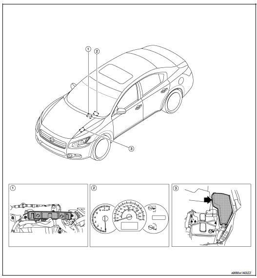
- BCM M16, M17, M18, M19, M20, M21 (view with instrument panel removed)
- Combination meter M24
- IPDM E/R E16, E17, E18, E200, E201, F10
 Signal buffer system
System Diagram
System Description
OUTLINE
BCM has the signal transmission function that outputs/transmits each
input/received signal to each unit.
Signal transmission function list
...
 Diagnosis system (BCM)
COMMON ITEM
COMMON ITEM : CONSULT Function (BCM - COMMON ITEM)
APPLICATION ITEM
CONSULT performs the following functions via CAN communication with BCM.
Direct Diagnostic Mode
De ...
Other materials:
STRG branch line circuit
Diagnosis Procedure
1.CHECK CONNECTOR
Turn the ignition switch OFF.
Disconnect the battery cable from the negative terminal.
Check the terminals and connectors of the steering angle sensor
for damage, bend and loose connection
(unit side and connector side).
2.CHECK HARNESS FOR OPE ...
Mode door control system
System Diagram
System Description
The mode door is automatically controlled by the temperature setting, ambient
temperature, in-vehicle temperature,
intake temperature and amount of sunload.
SYSTEM OPERATION
The A/C auto amp. receives data from each of the sensors.
The A/C auto amp. ...
Emission control information label
The emission control information label is attached
to the underside of the hood as shown.
Tire and loading information label
The cold tire pressure is shown on the Tire and
Loading Information label. The label is located as
shown.
Air conditioner specification label
The air condit ...
Nissan Maxima Owners Manual
- Illustrated table of contents
- Safety-Seats, seat belts and supplemental restraint system
- Instruments and controls
- Pre-driving checks and adjustments
- Monitor, climate, audio, phone and voice recognition systems
- Starting and driving
- In case of emergency
- Appearance and care
- Do-it-yourself
- Maintenance and schedules
- Technical and consumer information
Nissan Maxima Service and Repair Manual

0.0066