Nissan Maxima Service and Repair Manual: Oil
Description
MAINTENANCE OF OIL LEVEL
The compressor oil is circulating in the system together with the refrigerant. It is necessary to fill compressor with oil when replacing A/C system parts or when a large amount of refrigerant leakage is detected. It is important to always maintain oil level within the specified level, otherwise the following conditions may occur:
- Insufficient oil amount: Stuck compressor
- Excessive oil amount: Insufficient cooling (caused by insufficient heat exchange)
Oil Type : A/C System Oil Type S
Inspection
If a compressor is malfunctioning (internal noise, insufficient cooling), check the compressor oil.
1.COMPRESSOR OIL JUDGMENT
- Remove the compressor. Refer to HA-37, "Removal and Installation for Compressor".
- Sample compressor oil and judge below according to the figure.
Judgement result 1>>Replace compressor only.
Judgement result 2>>Replace
compressor and liquid tank.
Perform Oil Return Operation
CAUTION: If a large amount of refrigerant or oil leakage is detected, do not perform oil return operation.
- Start the engine and set to the following conditions:
- Engine speed: Idling to 1,200 rpm
- A/C switch: ON
- Fan (blower) speed: Maximum speed set
- Intake door position: Recirculation
- Temperature setting: Full cold
- Perform oil return operation for approximately 10 minutes.
- Stop the engine.
- Oil return operation is complete.
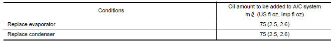
Oil Adjusting Procedure for Components Replacement Except Compressor
Fill with oil for the amount that is calculated according to the following conditions.
Example: Oil amount to be added when replacing evaporator and liquid tank [m (US fl oz, Imp fl oz)] = 45 (1.5, 1.6) + 15 (0.5, 0.5) + α
Oil Adjusting Procedure for Compressor Replacement
- New compressor
- Old compressor
- Recovery/recycling equipment
- Measuring cup X
- Measuring cup Y
- New oil
- Drain oil from the new compressor into clean container
- Record amount of oil recovered
- Add an additional 5 m (0.2 US fl oz, 0.2 Imp fl oz) of new oil when replacing liquid tank
- Install new oil equal to recorded amounts in measuring cups X plus Y
- Before connecting recovery/recycling equipment to vehicle, check
recovery/recycling equipment gauges.
No refrigerant pressure should be displayed. If NG, recover refrigerant from equipment lines.
- Connect recovery/recycling equipment to vehicle. Confirm refrigerant purity in supply tank using recovery/ recycling equipment and refrigerant identifier. If NG, refer to HAC-92, "Working with HFC-134a (R-134a)"
- Confirm refrigerant purity in vehicle A/C system using
recovery/recycling equipment and refrigerant identifier.
If NG, refer to HAC-92, "Working with HFC-134a (R-134a)".
- Discharge refrigerant into the refrigerant recovery/recycling equipment. Measure oil discharged into the recovery/recycling equipment.
- Drain the oil from the "old" (removed) compressor into a graduated container and recover the amount of oil drained.
- Drain the oil from the "new" compressor into a separate, clean container.
- Measure an amount of new oil installed equal to amount drained from "old" compressor. Add this oil to "new" compressor through the suction port opening.
- Measure an amount of new oil equal to the amount recovered during discharging. Add this oil to "new" compressor through the suction port opening.
- If the liquid tank also needs to be replaced, add an additional 5 m (0.2 US fl oz, 0.2 Imp fl oz) of oil at this time.
CAUTION: Do not add the 5 m (0.2 US fl oz, 0.2 Imp fl oz) of oil if only replacing the compressor and not the liquid tank.
 Refrigerant
Description
CONNECTION OF SERVICE TOOLS AND EQUIPMENT
Shut-off valve
A/C service valve
Recovery/recycling/recharging equipment
Refrigerant container (HFC-134a)
Weight scale (J-39650 ...
 Refrigeration system
Inspection
1.CHECK BLOWER MOTOR OPERATION
Check blower motor operation
2.CHECK COMPRESSOR OPERATION
Check compressor operatio
3.CHECK REFRIGERANT CYCLE PRESSURE
Connect recovery/recycling ...
Other materials:
L terminal circuit (open)
Description
The "L" terminal circuit controls the charge warning lamp. The charge warning
lamp turns ON when the ignition
switch is set to ON or START. When the generator is providing sufficient voltage
with the engine running,
the charge warning lamp turns OFF. If the charge warning lamp i ...
Steering switch
Description
When one of the steering wheel audio control switches is pushed, the
resistance in the steering wheel audio
control switch circuit changes, depending on which button is pushed.
Diagnosis Procedure
1.CHECK STEERING SWITCH RESISTANCE
Disconnect steering switch connector M88. ...
Diagnosis system (IPDM E/R)
Diagnosis Description
AUTO ACTIVE TEST
Description
In auto active test mode, the IPDM E/R sends a drive signal to the following
systems to check their operation.
Oil pressure warning lamp
Front wiper (LO, HI)
Parking lamps
Side marker lamps
License plate lamps
Tail lamps
Front f ...
Nissan Maxima Owners Manual
- Illustrated table of contents
- Safety-Seats, seat belts and supplemental restraint system
- Instruments and controls
- Pre-driving checks and adjustments
- Monitor, climate, audio, phone and voice recognition systems
- Starting and driving
- In case of emergency
- Appearance and care
- Do-it-yourself
- Maintenance and schedules
- Technical and consumer information
Nissan Maxima Service and Repair Manual

0.0069