Nissan Maxima Service and Repair Manual: Refrigeration system
Inspection
1.CHECK BLOWER MOTOR OPERATION
Check blower motor operation
2.CHECK COMPRESSOR OPERATION
Check compressor operatio
3.CHECK REFRIGERANT CYCLE PRESSURE
Connect recovery/recycling recharging equipment to the vehicle and perform the diagnosis with the gauge pressure. Refer to HA-19, "WITH COLOR DISPLAY : Trouble Diagnoses for Abnormal Pressure" (with color display) or HA-22, "WITH MONOCHROME DISPLAY : Trouble Diagnoses for Abnormal Pressure" (with monochrome display)
Performance Chart
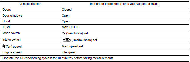
TEST CONDITION
Testing must be performed as follows
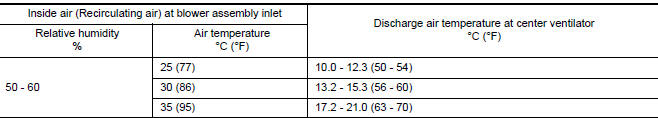
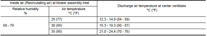
TEST READING
Recirculating-to-discharge Air Temperature Table
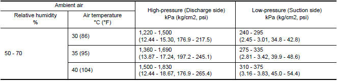
Ambient Air Temperature-to-operating Pressure Table
 Oil
Oil
Description
MAINTENANCE OF OIL LEVEL
The compressor oil is circulating in the system together with the
refrigerant. It is necessary to fill compressor with oil when replacing A/C
system parts or ...
 Performance test
Inspection
INSPECTION PROCEDURE
Connect recovery/recycling/recharging equipment (for HFC-134a) or
manifold gauge.
Start the engine, and set to the following condition.
Maintain tes ...
Other materials:
P2100, P2103 throttle control motor relay
Description
Power supply for the throttle control motor is provided to the ECM via the
throttle control motor relay. The throttle
control motor relay is controlled ON/OFF by the ECM. When the ignition switch is
turned ON, the ECM
sends an ON signal to throttle control motor relay and batter ...
Main line between ADP and DLC circuit
Diagnosis Procedure
1.CHECK CONNECTOR
Turn the ignition switch OFF.
Disconnect the battery cable from the negative terminal.
Check the following terminals and connectors for damage, bend and
loose connection (connector side
and harness side).
Harness connector B1
Harness connect ...
Main line between HVAC and A-bag circuit
Diagnosis Procedure
1.CHECK HARNESS CONTINUITY (OPEN CIRCUIT)
Turn the ignition switch OFF.
Disconnect the battery cable from the negative terminal.
Disconnect the following harness connectors.
A/C auto amp.
Harness connectors M1 and E30
Check the continuity between the A/C au ...
Nissan Maxima Owners Manual
- Illustrated table of contents
- Safety-Seats, seat belts and supplemental restraint system
- Instruments and controls
- Pre-driving checks and adjustments
- Monitor, climate, audio, phone and voice recognition systems
- Starting and driving
- In case of emergency
- Appearance and care
- Do-it-yourself
- Maintenance and schedules
- Technical and consumer information
Nissan Maxima Service and Repair Manual

0.0051