Nissan Maxima Service and Repair Manual: Key slot illumination
Description
Blinks when Intelligent Key insertion is required.
Component Function Check
1.CHECK FUNCTION
 With CONSULT
Check key slot illumination ("KEY SLOT ILLUMI") Active Test mode.
Diagnosis Procedure
Regarding Wiring Diagram information, refer to SEC-147, "Wiring Diagram" or SEC-128, "Wiring Diagram".
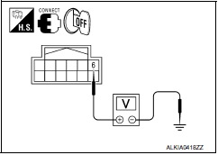
1.CHECK KEY SLOT ILLUMINATION OUTPUT SIGNAL
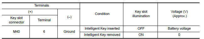
Check voltage between key slot harness connector M40 terminal 6 and ground.
2.CHECK KEY SLOT POWER SUPPLY CIRCUIT
-
Turn ignition switch OFF.
-
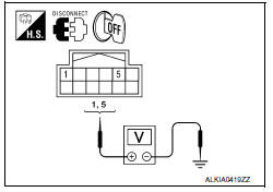
Disconnect key slot connector.
-
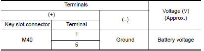
Check voltage between slot harness connector M40 terminal 1, 5 and ground.
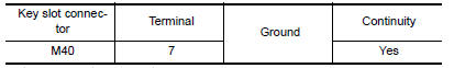
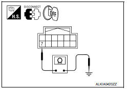
3.CHECK KEY SLOT GROUND CIRCUIT
Check continuity between key slot harness connector M40 terminal 7 and ground.
4.CHECK KEY SLOT CIRCUIT
-
Turn ignition switch OFF.
-
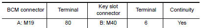
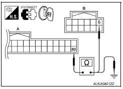
Disconnect BCM and key slot connector.
-
Check continuity between BCM harness connector M19 (A) terminal 80 and key slot harness connector M40 (B) terminal 6.
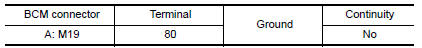
4. Check continuity between BCM harness connector M19 (A) terminal 80 and ground.
5.CHECK KEY SLOT
Refer to SEC-83, "Description".
6.CHECK INTERMITTENT INCIDENT
Refer to GI-41, "Intermittent Incident".
Inspection End.
 Key slot
Diagnosis Procedure
Regarding Wiring Diagram information, refer to SEC-147,
"Wiring Diagram" or SEC-128, "Wiring Diagram".
1.CHECK KEY SLOT POWER SUPPLY CIRCUIT
Turn ignition switch O ...
 Key cylinder switch
Description
The main power window and door lock/unlock switch detects
condition of the door key cylinder switch and
transmits to BCM as the LOCK or UNLOCK signal.
Component Function Check
1.CHE ...
Other materials:
Precautions on SRS
This SRS section contains important information
concerning the following systems:
Driver and front passenger supplemental
front-impact air bag (NISSAN Advanced Air
Bag System)
Front seat-mounted side-impact supplemental
air bag
Roof-mounted curtain side-impact and rollover
supplemen ...
Wiring diagram
AUTOMATIC DRIVE POSITIONER
Wiring Diagram
...
Precautions
Precaution for Supplemental Restraint System (SRS) "AIR BAG" and "SEAT
BELT
PRE-TENSIONER"
The Supplemental Restraint System such as "AIR BAG" and "SEAT BELT
PRE-TENSIONER", used along
with a front seat belt, helps to reduce the risk or severity of injury to the
driver ...
Nissan Maxima Owners Manual
- Illustrated table of contents
- Safety-Seats, seat belts and supplemental restraint system
- Instruments and controls
- Pre-driving checks and adjustments
- Monitor, climate, audio, phone and voice recognition systems
- Starting and driving
- In case of emergency
- Appearance and care
- Do-it-yourself
- Maintenance and schedules
- Technical and consumer information
Nissan Maxima Service and Repair Manual

0.0071