Nissan Maxima Service and Repair Manual: BCM (body control module)
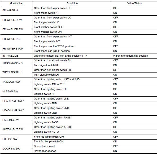
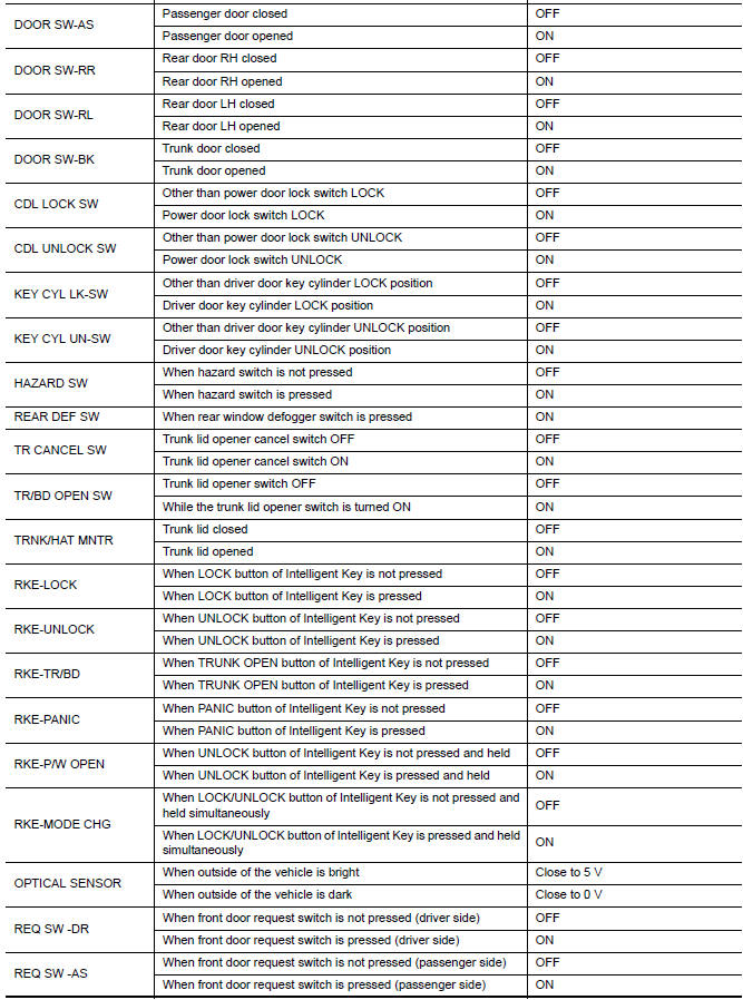
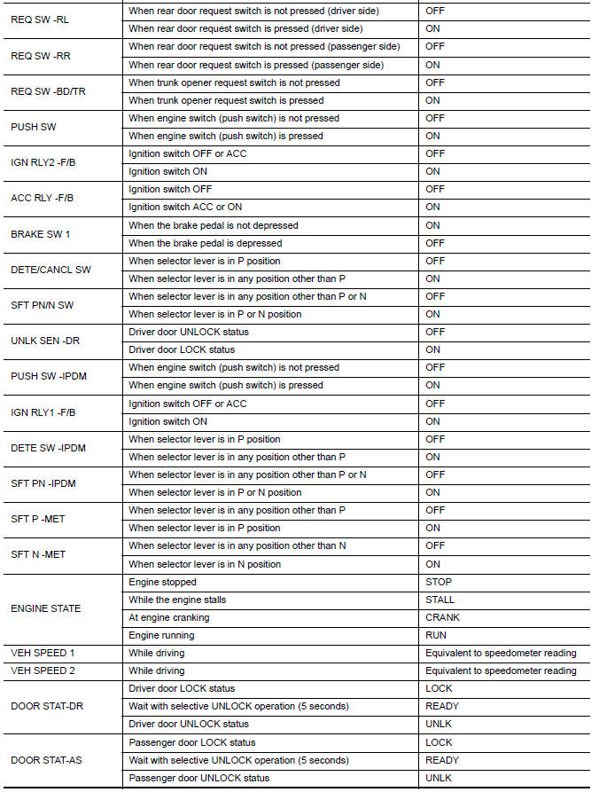
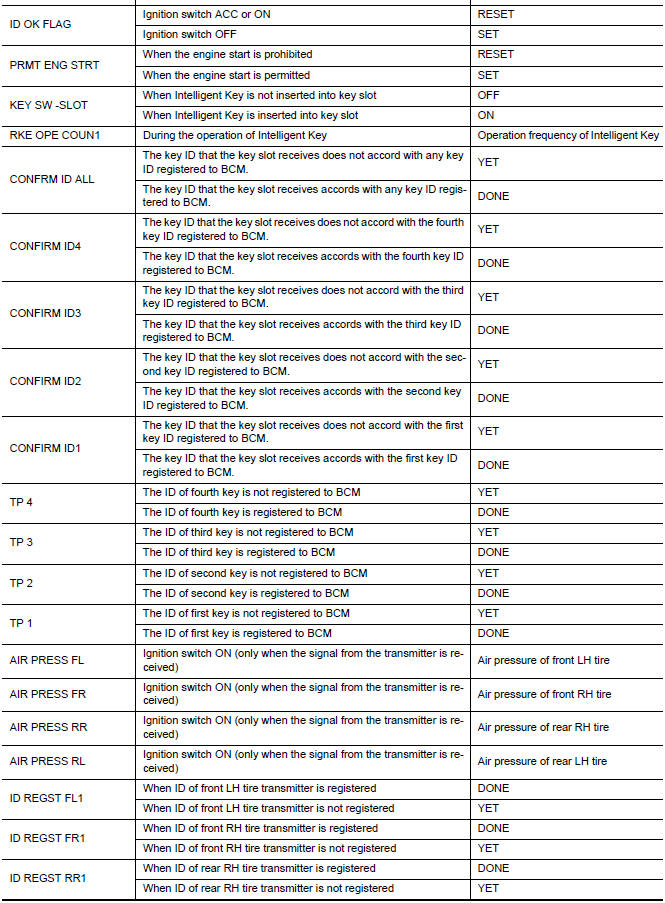
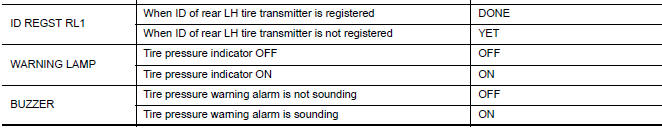
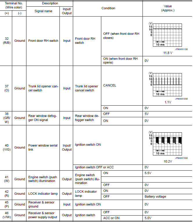
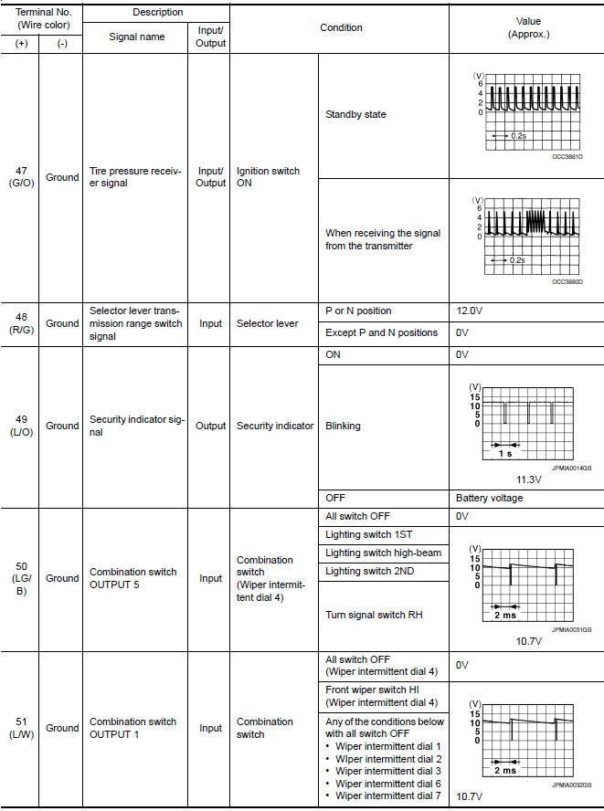
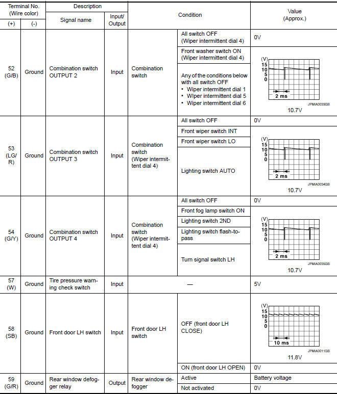
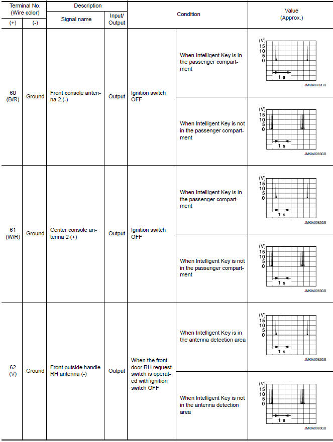
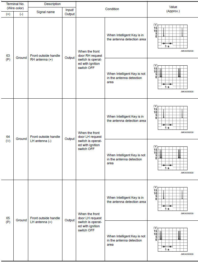
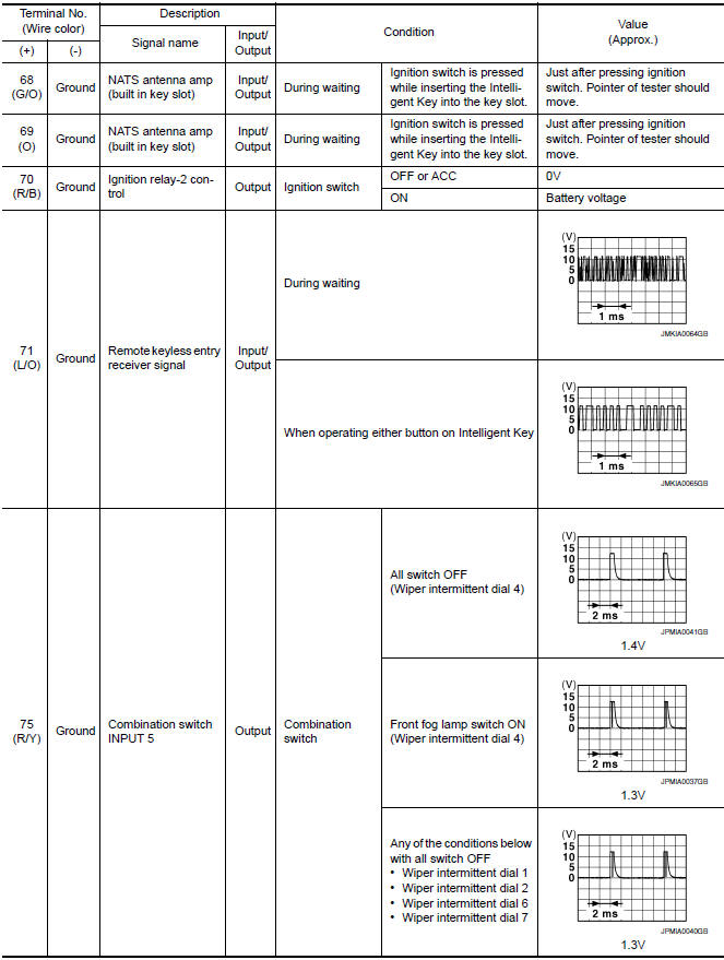
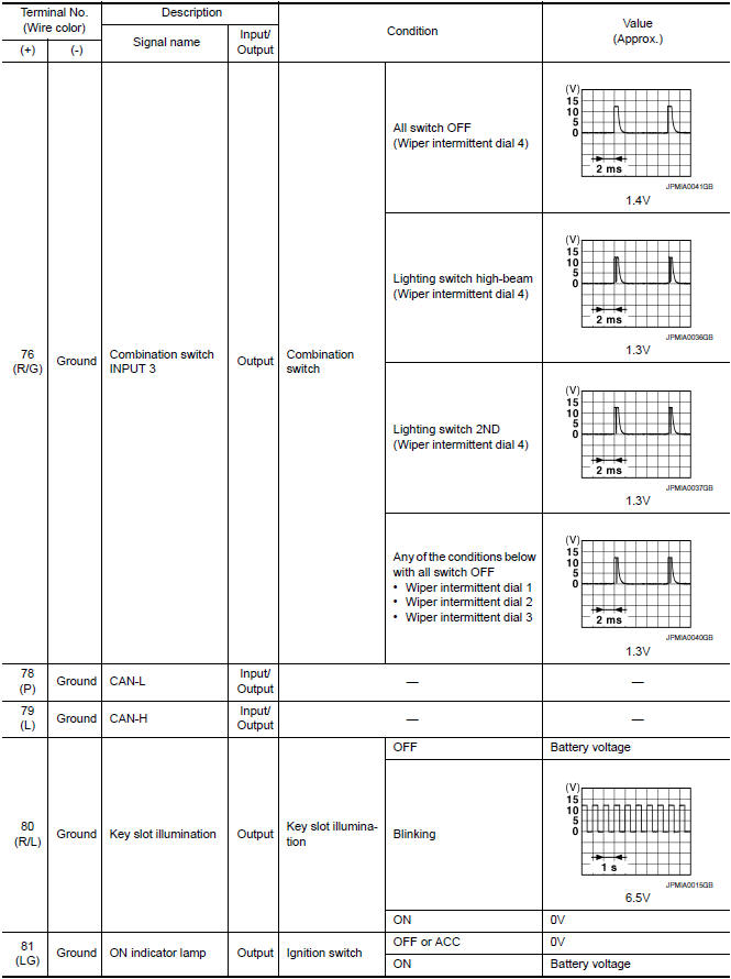
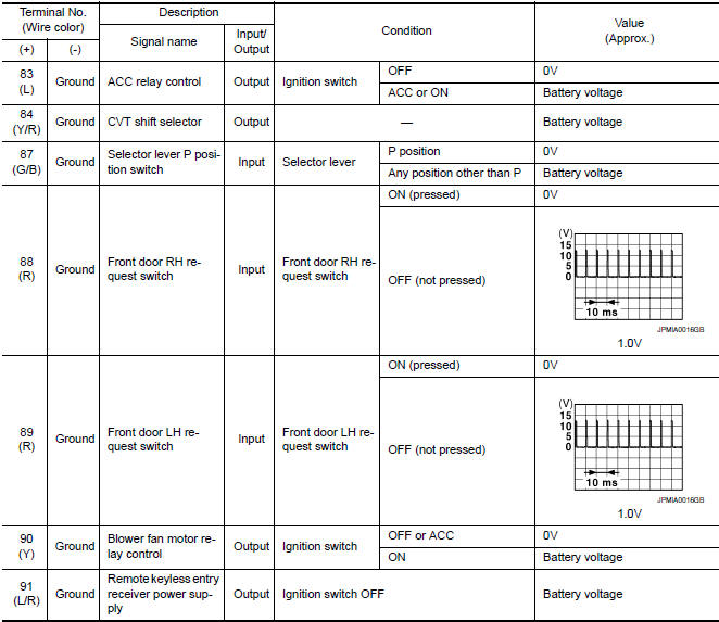
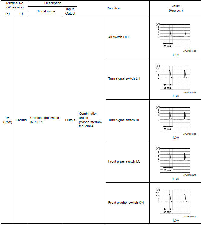
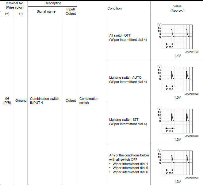
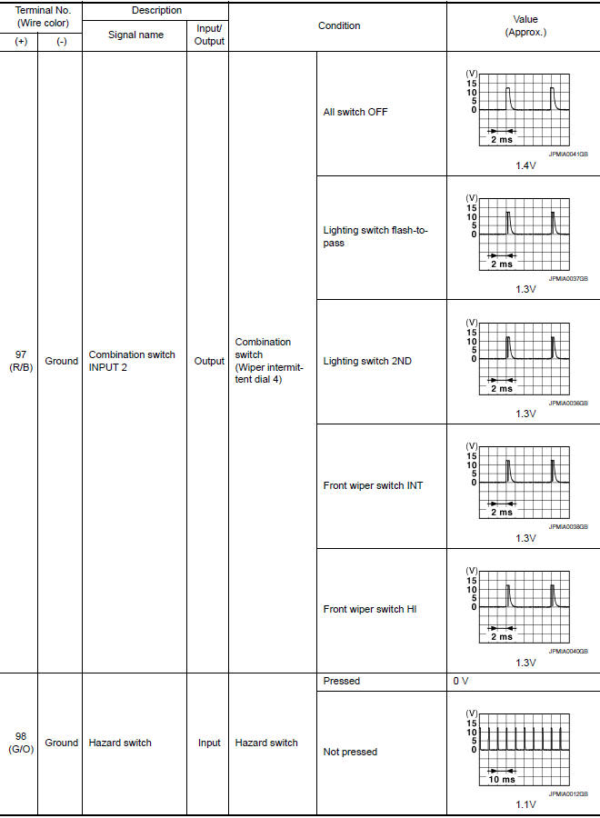
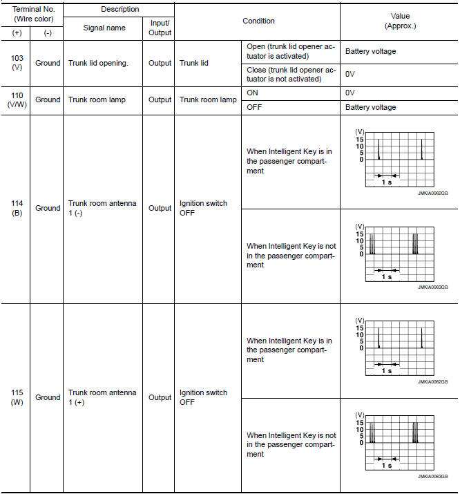
Reference Value
NOTE: The Signal Tech II Tool (J-50190) can be used to perform the following functions. Refer to the Signal Tech II User Guide for additional information.
- Activate and display TPMS transmitter IDs
- Display tire pressure reported by the TPMS transmitter
- Read TPMS DTCs
- Register TPMS transmitter IDs
- Check Intelligent Key relative signal strength
- Confirm vehicle Intelligent Key antenna signal strength
VALUES ON THE DIAGNOSIS TOOL
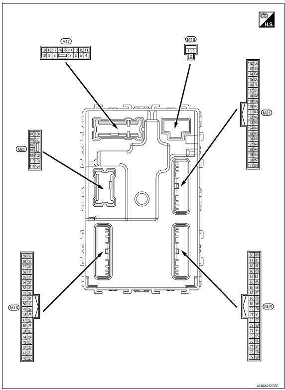
Terminal Layout
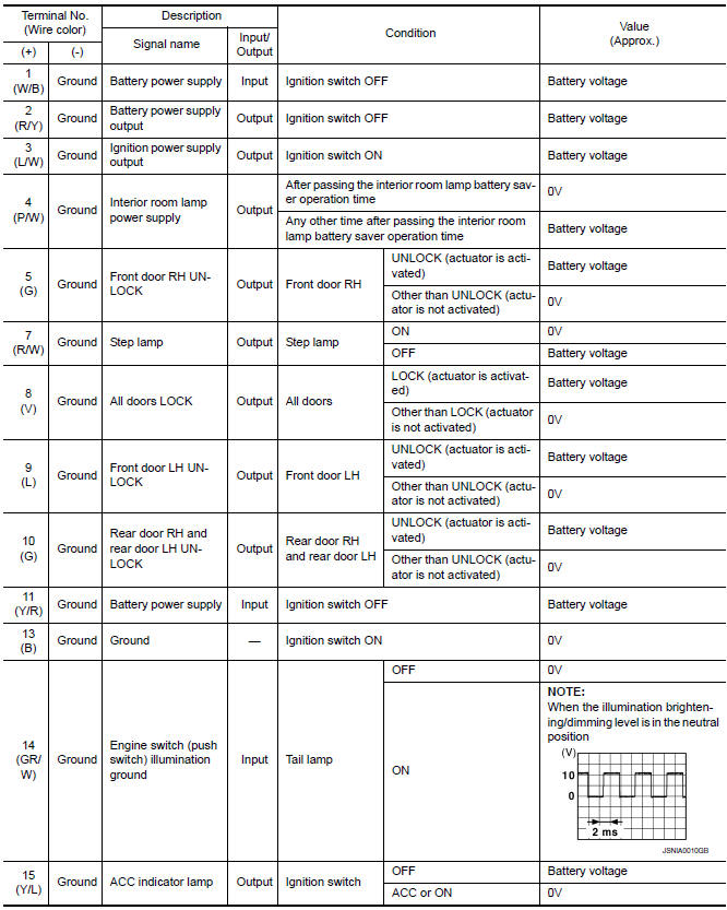
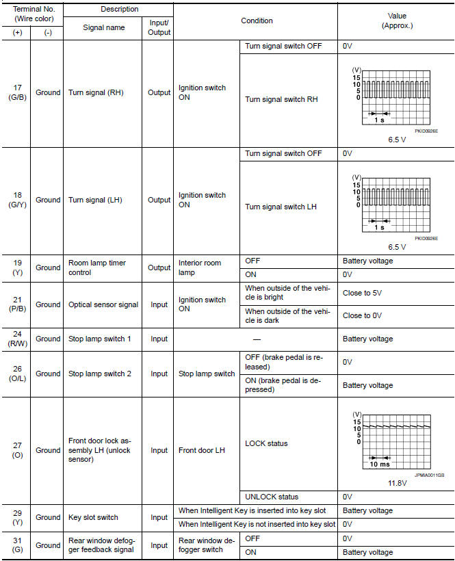
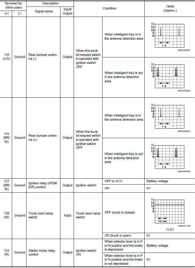
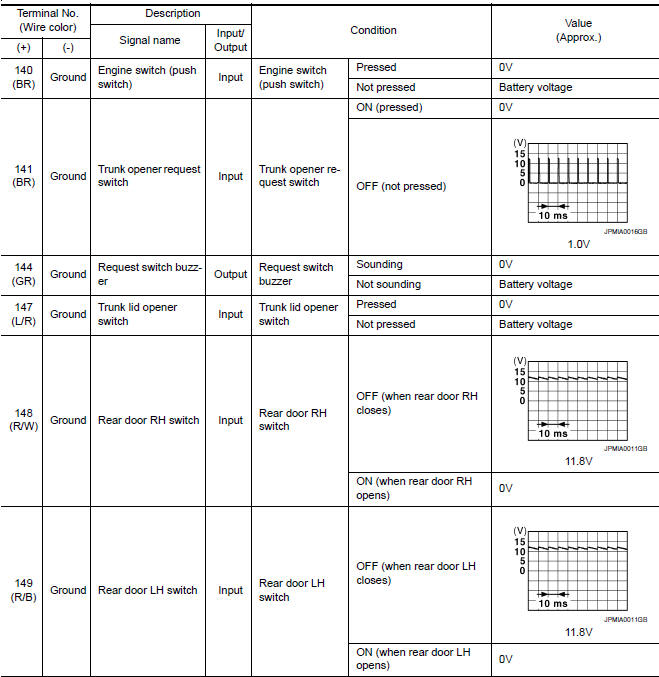
Physical Values
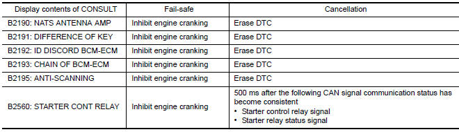
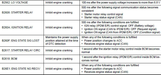
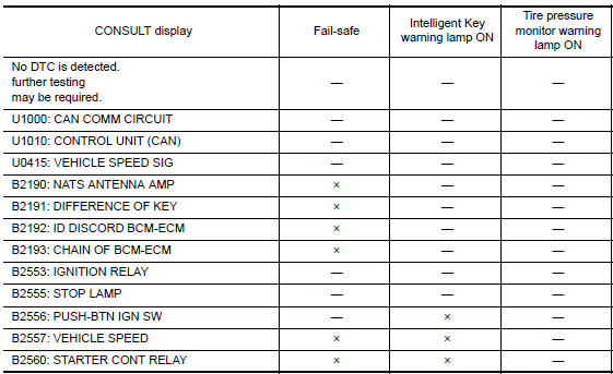
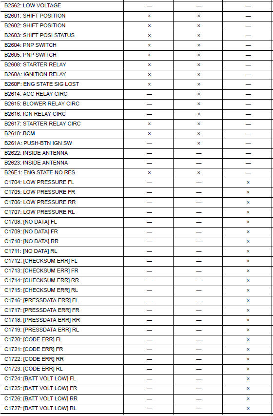
Fail Safe
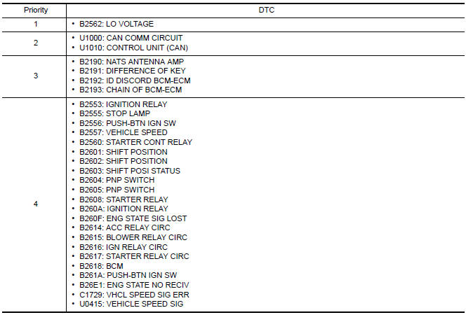
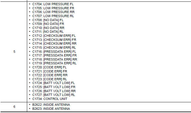
DTC Inspection Priority Chart
If some DTCs are displayed at the same time, perform inspections one by one based on the following priority chart.
DTC Index
NOTE: Details of time display
- CRNT: Displays when there is a malfunction now or after returning to the normal condition until turning ignition switch OFF → ON again.
- 1 - 39: Displayed if any previous malfunction is present when current condition is normal. It increases 1 → 2 → 3...38 → 39 after returning to the normal condition whenever ignition switch OFF → ON. The counter remains at 39 even if the number of cycles exceeds it. It is counted from 1 again when turning ignition switch OFF → ON after returning to the normal condition if the malfunction is detected again.


 IPDM E/R (intelligent power distribution module engine room)
Reference Value
VALUES ON THE DIAGNOSIS TOOL
TERMINAL LAYOUT
PHYSICAL VALUES
Fail Safe
CAN COMMUNICATION CONTROL
When CAN communication with ECM and BCM is imposs ...
Other materials:
HVAC branch line circuit
Diagnosis Procedure
1.CHECK CONNECTOR
Turn the ignition switch OFF.
Disconnect the battery cable from the negative terminal.
Check the terminals and connectors of the A/C auto amp. for
damage, bend and loose connection (unit
side and connector side).
2.CHECK HARNESS FOR OPEN CIRCUI ...
Front door speaker
Removal and Installation
REMOVAL
Remove the front door finisher. Refer to INT-18, "Removal and
Installation".
Remove the front door speaker screws (A).
Disconnect the harness connector from the front door speaker
(1) and remove.
Remove the front door speaker spacer screws (B) and ...
Parking, license plate and tail lamps
System Diagram
System Description
BCM (Body Control Module) controls parking, license plate and tail lamps
operation.
IPDM E/R (Intelligent Power Distribution Module Engine Room) operates
parking, license plate and tail lamps according to CAN communication
signals from BCM.
Comp ...
Nissan Maxima Owners Manual
- Illustrated table of contents
- Safety-Seats, seat belts and supplemental restraint system
- Instruments and controls
- Pre-driving checks and adjustments
- Monitor, climate, audio, phone and voice recognition systems
- Starting and driving
- In case of emergency
- Appearance and care
- Do-it-yourself
- Maintenance and schedules
- Technical and consumer information
Nissan Maxima Service and Repair Manual

0.0058