Nissan Maxima Service and Repair Manual: Parking, license plate and tail lamps
System Diagram
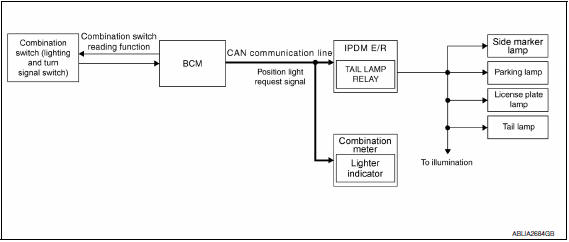
System Description
- BCM (Body Control Module) controls parking, license plate and tail lamps operation.
- IPDM E/R (Intelligent Power Distribution Module Engine Room) operates parking, license plate and tail lamps according to CAN communication signals from BCM.
Component Parts Location
- IPDM E/R E17, E18, E201
- BCM M16, M17, M18, M19 (view with combination meter removed)
- Combination switch (lighting and turn signal switch) M28
- Combination Meter M24
Component Description
PARKING, LICENSE PLATE AND TAIL LAMPS OPERATION
When the lighting switch is in 1ST position, BCM detects the LIGHTING SWITCH 1ST POSITION ON. The BCM sends a parking light ON request through the CAN communication lines to the IPDM E/R. The IPDM E/R then activates the tail lamp relay which sends power to the parking and instrument illumination circuits.
EXTERIOR LAMP BATTERY SAVER CONTROL
With the combination switch (lighting and turn signal switch) in the 2nd position and the ignition switch is turned from ON or ACC to OFF, the battery saver feature is activated.
Under this condition, the headlamps remain illuminated for 5 minutes unless the lighting switch position is changed. If the lighting switch position is changed, then the headlamps are turned off.
This setting can be changed by CONSULT. Refer to EXL-193, "BATTERY SAVER : CONSULT Function (BCM - BATTERY SAVER)".
 Turn signal and hazard warning lamps
System Diagram
System Description
BCM (Body Control Module) controls turn signal lamp (RH and LH) and
hazard warning lamp operation
Combination meter operates turn signal indicator (RH and ...
 Combination switch reading system
System Diagram
System Description
OUTLINE
BCM reads the status of the combination switch (light, turn
signal, wiper and washer) and recognizes the status of each switch.
BCM has a combina ...
Other materials:
Outside key antenna
Description
Detects whether Intelligent Key is outside the vehicle.
Integrated in front outside handle (driver side, passenger side) and installed
in rear bumper.
Component Function Check
NOTE:
The Signal Tech II Tool (J-50190) can be used to perform the following
functions. Refer to t ...
Front fog lamp aiming adjustment
Description
PREPARATION BEFORE ADJUSTING
CAUTION: Do not use organic solvent
(thinner, gasoline etc.).
NOTE: For
details, refer to the regulations in your own country.
Before performing
aiming adjustment, check the following.
Keep all tires inflated to correct pressure.
Place vehicle ...
Glass lid
Removal and Installation
REMOVAL
CAUTION:
Always work with a helper.
Handle glass lid with care to prevent damage.
NOTE: For easier and more accurate
installation, always mark each point before removal.
Open sunshade.
Tilt glass lid up, then slide rearward to expose all the g ...
Nissan Maxima Owners Manual
- Illustrated table of contents
- Safety-Seats, seat belts and supplemental restraint system
- Instruments and controls
- Pre-driving checks and adjustments
- Monitor, climate, audio, phone and voice recognition systems
- Starting and driving
- In case of emergency
- Appearance and care
- Do-it-yourself
- Maintenance and schedules
- Technical and consumer information
Nissan Maxima Service and Repair Manual

0.0065