Nissan Maxima Service and Repair Manual: Service Data And Specifications (SDS)
General Specification
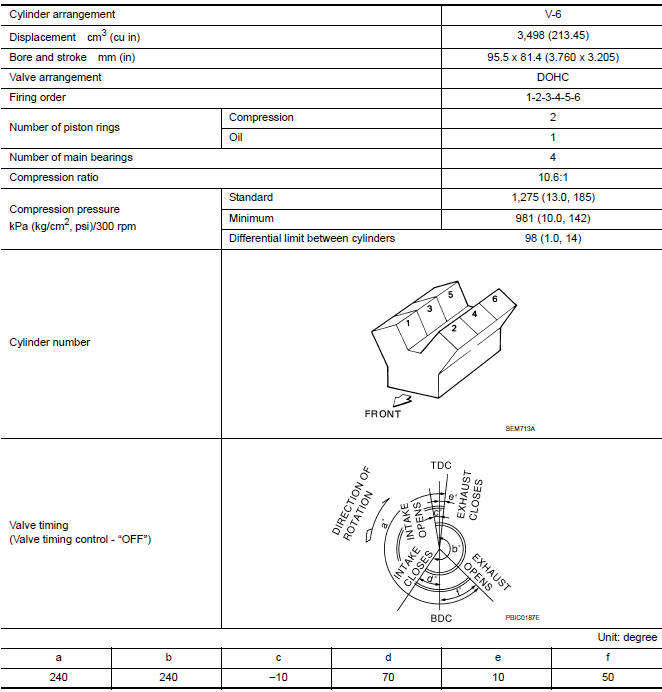
GENERAL SPECIFICATIONS
Drive Belt
DRIVE BELT

Spark Plug
SPARK PLUG
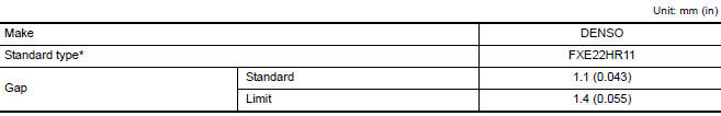
*: Always check with the Parts Department for the latest parts information.
Intake Manifold
INTAKE MANIFOLD

Exhaust Manifold
EXHAUST MANIFOLD

Camshaft
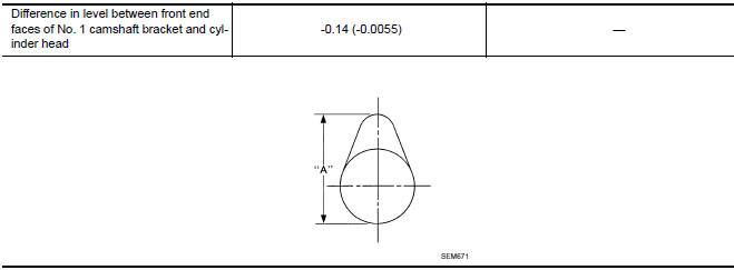
CAMSHAFT
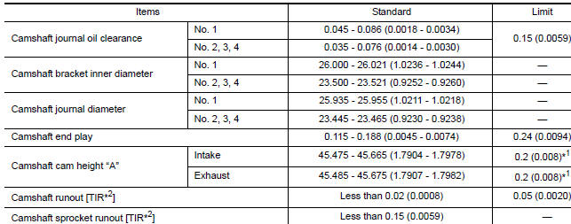
*1: Cam wear limit
*2: Total indicator reading
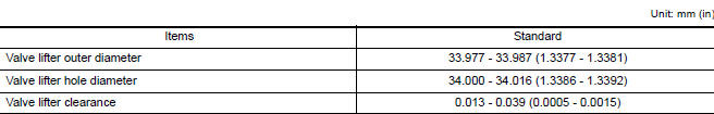
VALVE LIFTER
VALVE CLEARANCE
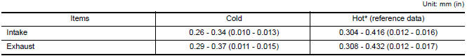
*: Approximately 80C (176F)
AVAILABLE VALVE LIFTER
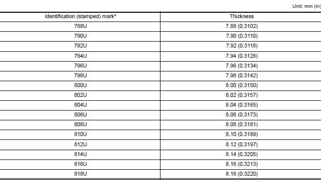
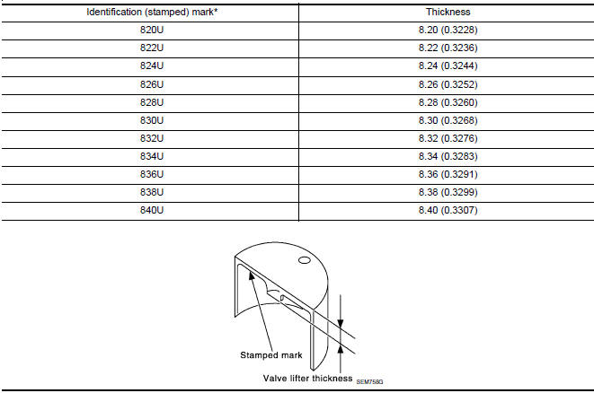
*: Always check with the Parts Department for the latest parts information.
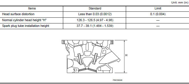
Cylinder Head
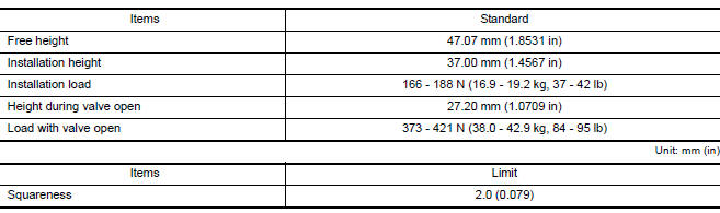
CYLINDER HEAD
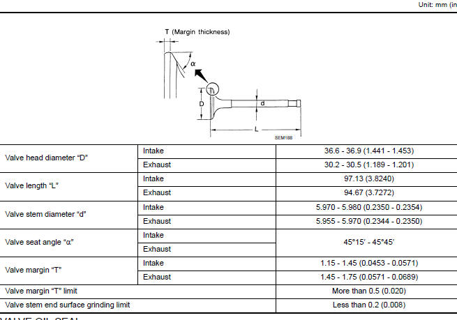
VALVE DIMENSIONS
VALVE OIL SEAL

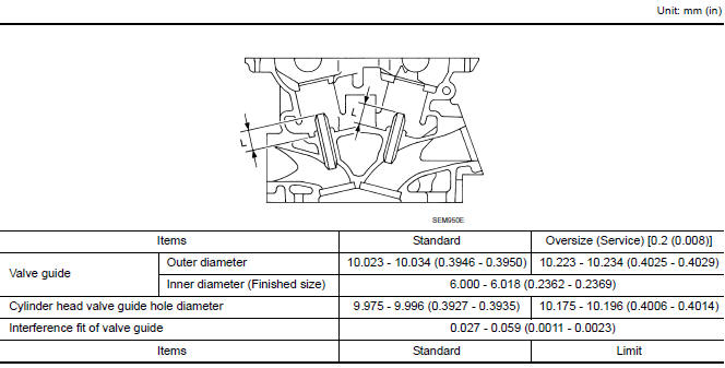
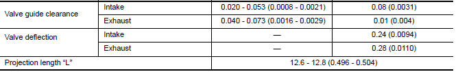
VALVE GUIDE
VALVE SEAT
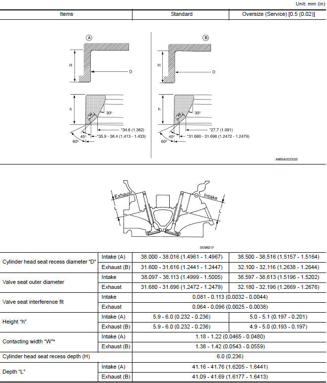
*:Machining data
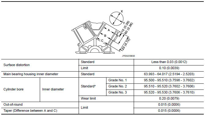
VALVE SPRING
Cylinder Block
CYLINDER BLOCK
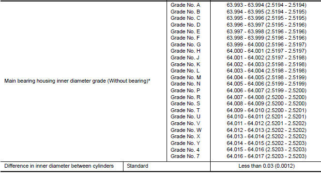
*: Always check with the Parts Department for the latest parts information.
AVAILABLE PISTON
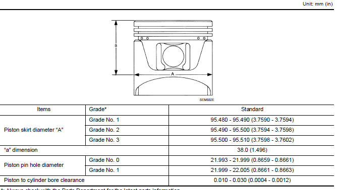
*: Always check with the Parts Department for the latest parts information.
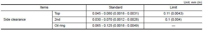
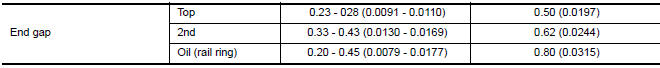
PISTON RING
PISTON PIN
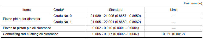
*: Always check with the Parts Department for the latest parts information.
CONNECTING ROD
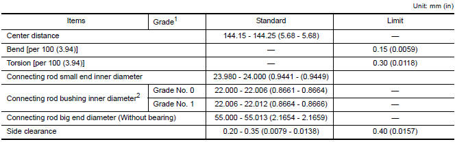
1: Always check with the Parts Department for the latest parts information.
2: After installing in connecting rod
CRANKSHAFT
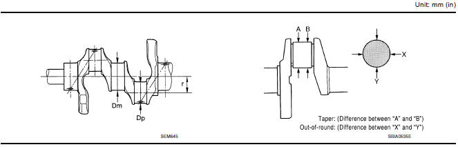
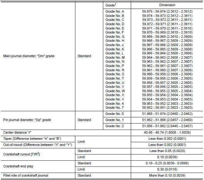
1: Always check with the Parts Department for the latest parts information.
2: Total indicator reading
Main Bearing
MAIN BEARING
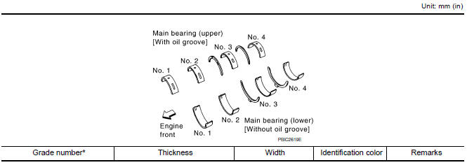
*: Always check with the Parts Department for the latest parts information.
UNDERSIZE

MAIN BEARING OIL CLEARANCE

*: Actual clearance
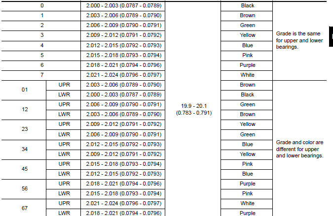
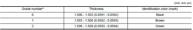
Connecting Rod Bearing
CONNECTING ROD BEARING
*: Always check with the Parts Department for the latest parts information.
UNDERSIZE

CONNECTING ROD BEARING OIL CLEARANC

*: Actual clearance
Drive Plate
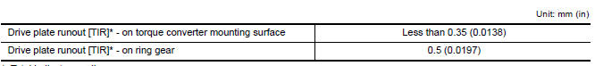
*: Total indicator reading
 Oil Seal
Removal and Installation of Valve Oil Seal
REMOVAL
Turn crankshaft until the cylinder requiring new oil seals is at
TDC. This will prevent valve from dropping into cylinder.
CAUTION: When r ...

Other materials:
Normal operating condition
Description
Symptom
Result
Slight vibrations are felt on the brake pedal and the operation
noises occur, when VDC, TCS or ABS is activated.
This is a normal condition
due to the VDC,
TCS or ABS activation.
Stopping distance is longer than that of v ...
Charging system
System Diagram
System Description
The generator provides DC voltage to operate the vehicle's electrical system
and to keep the battery charged.
The voltage output is controlled by the IC regulator.
Component Description
...
Power supply routing circuit
Wiring Diagram -Battery Power Supply -
Wiring Diagram -Accessory Power Supply -
Wiring Diagram -Ignition Power Supply -
Fuse
If fuse is blown, be sure to eliminate cause of malfunction before
installing new fuse.
U ...
Nissan Maxima Owners Manual
- Illustrated table of contents
- Safety-Seats, seat belts and supplemental restraint system
- Instruments and controls
- Pre-driving checks and adjustments
- Monitor, climate, audio, phone and voice recognition systems
- Starting and driving
- In case of emergency
- Appearance and care
- Do-it-yourself
- Maintenance and schedules
- Technical and consumer information
Nissan Maxima Service and Repair Manual

0.0061