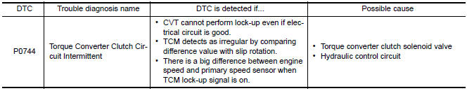
Nissan Maxima Service and Repair Manual: P0744 torque converter
Description
This malfunction is detected when the torque converter clutch does not lock-up as instructed by the TCM. This is not only caused by electrical malfunctions (circuits open or shorted), but also by mechanical malfunctions such as control valve sticking, improper solenoid valve operation, etc.
DTC Logic
DTC DETECTION LOGIC
DTC CONFIRMATION PROCEDURE
CAUTION: Always drive vehicle at a safe speed.
NOTE: Immediately after performing any "DTC CONFIRMATION PROCEDURE", always turn ignition switch OFF.
Then wait at least 10 seconds before performing the next test.
1.CHECK DTC DETECTION
 With CONSULT
- Turn ignition switch ON.
- Select "Data Monitor" in "TRANSMISSION".
- Start engine and maintain the following condition for at least 30 seconds.
ACC PEDAL OPEN : More than 1.0/8
RANGE : "D" position
VEHICLE SPEED : Constant speed of more than 40 km/h (25 MPH)
 With GST
Follow the procedure "With CONSULT".
Diagnosis Procedure
1.CHECK LINE PRESSURE
Perform line pressure test. Refer to TM-162, "Inspection and Judgment".
2.CHECK TORQUE CONVERTER CLUTCH SOLENOID VALVE
- Turn ignition switch OFF.
- Disconnect CVT unit connector.
- Check torque converter clutch solenoid valve. Refer to TM-70, "Component Inspection (Torque Converter Clutch Solenoid Valve)".
3.CHECK LOCK-UP SELECT SOLENOID VALVE
Check lock-up select solenoid valve. Refer to TM-70, "Component Inspection (Lock-up Select Solenoid Valve)".
4.CHECK SECONDARY SPEED SENSOR SYSTEM
Check secondary speed sensor system. Refer to TM-60, "DTC Logic".
5.CHECK PRIMARY SPEED SENSOR SYSTEM
Check primary speed sensor system. Refer to TM-57, "DTC Logic".
6.DETECT MALFUNCTIONING ITEMS
Check TCM connector pin terminals for damage or loose connection with harness connector.
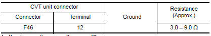
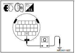
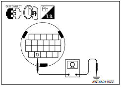
Component Inspection (Torque Converter Clutch Solenoid Valve)
1.CHECK TORQUE CONVERTER CLUTCH SOLENOID VALVE
Check resistance between CVT unit connector terminal and ground.
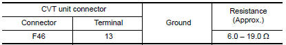
Component Inspection (Lock-up Select Solenoid Valve)
1.CHECK LOCK-UP SELECT SOLENOID VALVE
Check resistance between CVT unit connector terminal and ground.
 P0740 torque converter
Description
The torque converter clutch solenoid valve is activated by the TCM
in response to signals sent from the vehicle
speed and accelerator pedal position sensors. Lock-up piston ...
 P0745 pressure control solenoid A
Description
The line pressure solenoid valve regulates the oil pump discharge pressure to
suit the driving condition in
response to a signal sent from the TCM.
DTC Logic
DTC DETECTION LOGIC
...
Other materials:
Diagnosis and repair workflow
Work Flow
OVERALL SEQUENCE
DETAILED FLOW
1.CHECK SYMPTOM
Check the malfunction symptoms by performing the following items.
Interview the customer to obtain the malfunction information (conditions
and environment when the malfunction
occurred).
Check the symptom.
2.SELF-DIAGNOS ...
Precautions
PRECAUTION
Precaution for Supplemental Restraint System (SRS) "AIR BAG" and
"SEAT BELT PRE-TENSIONER "
The Supplemental Restraint System such as "AIR BAG" and "SEAT BELT PRE-TENSIONER
",
used along
with a front seat belt, helps to reduce the risk or ...
Clip list
Descriptions for Clips
Replace any clips which are damaged during removal or installation.
...
Nissan Maxima Owners Manual
- Illustrated table of contents
- Safety-Seats, seat belts and supplemental restraint system
- Instruments and controls
- Pre-driving checks and adjustments
- Monitor, climate, audio, phone and voice recognition systems
- Starting and driving
- In case of emergency
- Appearance and care
- Do-it-yourself
- Maintenance and schedules
- Technical and consumer information
Nissan Maxima Service and Repair Manual

0.01