Nissan Maxima Service and Repair Manual: P0740 torque converter
Description
- The torque converter clutch solenoid valve is activated by the TCM in response to signals sent from the vehicle speed and accelerator pedal position sensors. Lock-up piston operation will then be controlled.
- Lock-up operation, however, is prohibited when CVT fluid temperature is too low.
- When the accelerator pedal is depressed (less than 2.0/8) in lock-up condition, the engine speed should not change abruptly. If there is a big jump in engine speed, there is no lock-up.
DTC Logic
DTC DETECTION LOGIC
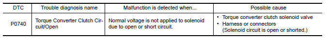
DTC CONFIRMATION PROCEDURE
NOTE: Immediately after performing any "DTC CONFIRMATION PROCEDURE", always turn ignition switch OFF.
Then wait at least 10 seconds before performing the next test.
1.CHECK DTC DETECTION
 With CONSULT
- Turn ignition switch ON.
- Wait at least 10 consecutive seconds.
- Perform "Self Diagnostic Results" in "TRANSMISSION".
 With GST
Follow the procedure "With CONSULT".
Diagnosis Procedure
Regarding Wiring Diagram information, refer to TM-126, "Wiring Diagram".
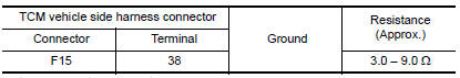
1.CHECK TORQUE CONVERTER CLUTCH SOLENOID VALVE CIRCUIT
- Turn ignition switch OFF.
- Disconnect TCM connector.
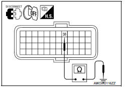
- Check resistance between TCM vehicle side harness connector terminal and ground.
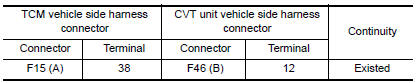
2.CHECK HARNESS BETWEEN TCM AND CVT UNIT (TORQUE CONVERTER CLUTCH SOLENOID VALVE) (PART 1)
- Disconnect CVT unit connector.
- Check continuity between TCM vehicle side harness connector terminal and CVT unit vehicle side harness connector terminal.
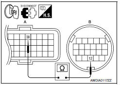
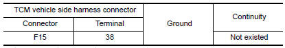
3.CHECK HARNESS BETWEEN TCM AND CVT UNIT (TORQUE CONVERTER CLUTCH SOLENOID VALVE) (PART 2)
Check continuity between TCM vehicle side harness connector terminal and ground.
4.CHECK TORQUE CONVERTER CLUTCH SOLENOID VALVE
Check torque converter clutch solenoid valve. Refer to TM-68, "Component Inspection (Torque Converter Clutch Solenoid Valve)".
5.DETECT MALFUNCTIONING ITEMS
Check TCM connector pin terminals for damage or loose connection with harness connector.
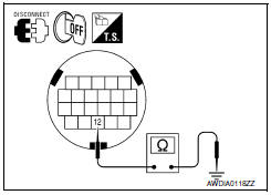
Component Inspection (Torque Converter Clutch Solenoid Valve)
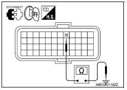
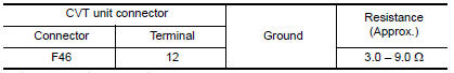
1.CHECK TORQUE CONVERTER CLUTCH SOLENOID VALVE
Check resistance between CVT unit connector terminal and ground.
 P0730 incorrect gear ratio
Description
TCM selects the gear ratio using the engine load (throttle position), the
primary pulley revolution speed, and
the secondary pulley revolution speed as input signals. Then it changes ...
 P0744 torque converter
Description
This malfunction is detected when the torque converter clutch does not
lock-up as instructed by the TCM. This
is not only caused by electrical malfunctions (circuits open or shorted), ...
Other materials:
DTC/circuit diagnosis
POWER SUPPLY AND GROUND CIRCUIT
COMBINATION METER
COMBINATION METER : Diagnosis Procedure
Regarding Wiring Diagram information, refer to MWI-87, "Wiring Diagram".
1.CHECK FUSES
Check for blown combination meter fuses.
2.POWER SUPPLY CIRCUIT CHECK
Disconnect combination meter connector.
...
Antenna AMP
Removal and Installation
REMOVAL
Remove the rear pillar finisher RH. Refer to INT-23, "Exploded
View".
Detach the antenna amp. harness clip (A).
Disconnect the harness connectors (B) from the antenna amp.
(1).
Remove the antenna amp. screw (C) and the antenna amp. (1).
INSTALLAT ...
Service data and specifications (SDS)
Steering Wheel
Steering Angle
Steering Column
STEERING COLUMN LENGTH
STEERING COLUMN ROTATING TORQUE
TILT MECHANISM OPERATING RANGE
Steering Gear
STEERING OUTER SOCKET AND INNER SOCKET
RACK STROKE
RACK SLIDING FORCE
Oil Pump
Steering Fluid
...
Nissan Maxima Owners Manual
- Illustrated table of contents
- Safety-Seats, seat belts and supplemental restraint system
- Instruments and controls
- Pre-driving checks and adjustments
- Monitor, climate, audio, phone and voice recognition systems
- Starting and driving
- In case of emergency
- Appearance and care
- Do-it-yourself
- Maintenance and schedules
- Technical and consumer information
Nissan Maxima Service and Repair Manual

0.0075