Nissan Maxima Service and Repair Manual: Wiring diagram
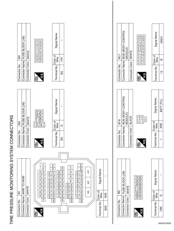
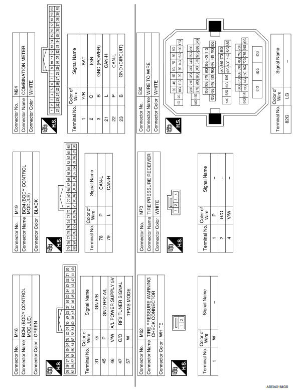
TIRE PRESSURE MONITORING SYSTEM
Wiring Diagram
 ECU diagnosis information
BCM (BODY CONTROL MODULE)
Reference Value
NOTE: The Signal Tech II Tool (J-50190) can be used
to perform the following functions. Refer to the Signal Tech II User Guide
for additional informatio ...

Other materials:
Intake valve timing control
System Diagram
System Description
INPUT/OUTPUT SIGNAL CHART
*: This signal is sent to the ECM via the CAN communication line
SYSTEM DESCRIPTION
This mechanism hydraulically controls cam phases continuously with the fixed
operating angle of the intake
valve.
The ECM receives s ...
Opener operation
To open the trunk lid, push the opener switch.
To close the trunk lid, lower and push the trunk lid
down securely.
NOTE:
You can open the trunk lid with the Intelligent
Key. For additional information, refer
to "NISSAN Intelligent Key" in this section.
Cancel switch
When the cancel ...
Precaution
Precaution for Supplemental Restraint System (SRS) "AIR BAG" and
"SEAT BELT PRE-TENSIONER"
The Supplemental Restraint System such as "AIR BAG" and "SEAT BELT
PRE-TENSIONER", used along with a front seat belt, helps to reduce the risk
or severity of injury to the driver and front passenger for ...
Nissan Maxima Owners Manual
- Illustrated table of contents
- Safety-Seats, seat belts and supplemental restraint system
- Instruments and controls
- Pre-driving checks and adjustments
- Monitor, climate, audio, phone and voice recognition systems
- Starting and driving
- In case of emergency
- Appearance and care
- Do-it-yourself
- Maintenance and schedules
- Technical and consumer information
Nissan Maxima Service and Repair Manual

0.0051