Nissan Maxima Service and Repair Manual: U1000 CAN comm circuit
Description
CAN (Controller Area Network) is a serial communication line for real time applications. It is an on-vehicle multiplex communication line with high data communication speed and excellent error detection ability. Modern vehicle is equipped with many electronic control unit, and each control unit shares information and links with other control units during operation (not independent). In CAN communication, control units are connected with 2 communication lines (CAN-H line, CAN-L line) allowing a high rate of information transmission with less wiring. Each control unit transmits/receives data but selectively reads required data only.
CAN Communication Signal Chart, refer to LAN-24, "CAN Communication Signal Chart".
DTC Logic
DTC DETECTION LOGIC
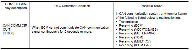
Diagnosis Procedure
1.PERFORM SELF DIAGNOSTIC
-
Turn ignition switch ON and wait for 2 seconds or more.
-
Check "Self Diagnostic Result".

 U1010 control unit (CAN)
DTC Logic
DTC DETECTION LOGIC
Diagnosis Procedure
1. REPLACE BCM
When DTC U1010 is detected, replace BCM.
Replace BCM. Refer to BCS-79, "Removal and
Installation". ...
Other materials:
Evap leak check
Inspection
CAUTION:
Never use compressed air or a high pressure pump.
Never exceed 4.12 kPa (0.042 kg/cm2, 0.6 psi) of pressure in
EVAP system.
NOTE:
Do not start engine.
Improper installation of EVAP service port adapter (commercial
service tool) ...
Steering column
Without Electric Motor
-4. Steering column assembly nut tightening order
Steering wheel
Combination switch and spiral cable
Steering column assembly
Hole cover seal
Herbie clip
Hole cover
Lower shaft assembly
With Electric Motor
-4. Steering column assembly ...
Rear view monitor system
System Diagram
System Description
When the shift selector is in the R position, the display shows a view to the
rear of the vehicle. Lines which indicate the vehicle clearance and distances
are also displayed.
Component Parts Location
Tweeter LH M143
Tweeter RH M144
AV control ...
Nissan Maxima Owners Manual
- Illustrated table of contents
- Safety-Seats, seat belts and supplemental restraint system
- Instruments and controls
- Pre-driving checks and adjustments
- Monitor, climate, audio, phone and voice recognition systems
- Starting and driving
- In case of emergency
- Appearance and care
- Do-it-yourself
- Maintenance and schedules
- Technical and consumer information
Nissan Maxima Service and Repair Manual

0.006