Nissan Maxima Service and Repair Manual: C1115 ABS sensor [abnormal signal]
Description
When the sensor rotor rotates, the magnetic field changes. It converts the magnetic field changes to current signals (rectangular wave) and transmits them to the ABS actuator and electric unit (control unit).
DTC Logic
DTC DETECTION LOGIC
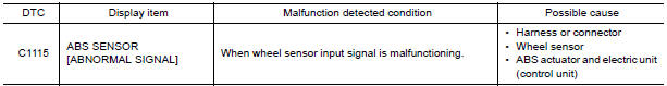
DTC CONFIRMATION PROCEDURE
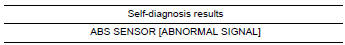
1.CHECK SELF-DIAGNOSIS RESULTS
Check the self-diagnosis results.
Diagnosis Procedure
CAUTION: Do not check between wheel sensor terminals.
1.CONNECTOR INSPECTION
- Disconnect ABS actuator and electric unit (control unit) connector and wheel sensor of malfunctioning code.
- Check terminals for deformation, disconnection, looseness or damage.
2.CHECK WHEEL SENSOR OUTPUT SIGNAL
- Connect ABS active wheel sensor tester (J-45741) to wheel sensor using appropriate adapter.
- Turn on the ABS active wheel sensor tester power switch. NOTE: The green POWER indicator should illuminate. If the POWER indicator does not illuminate, replace the battery in the ABS active wheel sensor tester before proceeding.
- Spin the wheel of the vehicle by hand and observe the red SENSOR indicator on the ABS active wheel sensor tester. The red SENSOR indicator should flash on and off to indicate an output signal. NOTE: If the red SENSOR indicator illuminates but does not flash, reverse the polarity of the tester leads and retest.
3.CHECK TIRES
Check the inflation pressure, wear and size of each tire.
4.CHECK WHEEL BEARINGS
Check wheel bearing axial end play
5.CHECK WIRING HARNESS FOR SHORT CIRCUIT
- Disconnect ABS actuator and electric unit (control unit) connector and wheel sensor of malfunctioning code.
- Check continuity between front wheel sensor connector terminals (A), rear wheel sensor connector terminals (B) and ground
: Continuity should not exist.
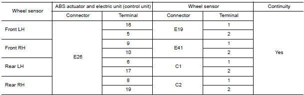
6.CHECK WIRING HARNESS FOR OPEN CIRCUIT
Check continuity between ABS actuator and electric unit (control unit) connector and the malfunctioning wheel sensor connector.
Component Inspection
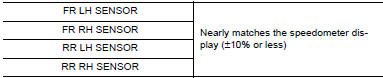
1.CHECK DATA MONITOR
On "DATA MONITOR", select "FR LH SENSOR", "FR RH SENSOR", "RR LH SENSOR", and "RR RH SENSOR", and check the vehicle speed.

Special Repair Requirement
1.ADJUSTMENT OF STEERING ANGLE SENSOR NEUTRAL POSITION
Always perform the neutral position adjustment for the steering angle sensor, when replacing the ABS actuator and electric unit (control unit).
 C1114 main relay
Description
Activates or deactivates each solenoid valve according to the signals
transmitted by the ABS actuator and
electric unit (control unit).
DTC Logic
DTC DETECTION LOGIC
DTC CONFIR ...
 C1116 stop lamp SW
Description
The stop lamp switch transmits the stop lamp switch signal (ON/OFF) to the
ABS actuator and electric unit
(control unit).
DTC Logic
DTC DETECTION LOGIC
DTC CONFIRMATION PROCEDU ...
Other materials:
Rear spoiler
Exploded View
Rear spoiler assembly
High-mounted stop lamp harness connector
Harness grommet
Removal and Installation
Removal
Remove trunk lid finisher. Refer to INT-36, "Removal and Installation".
Disconnect the harness connector (1) from the high-mounted stop lamp.
Remo ...
P1615 diffrence of key
Description
Performs ID verification through BCM and Intelligent Key
when push-button ignition switch is pressed.
Prohibits the start of engine when an unregistered ID of Intelligent Key is
used.
DTC Logic
DTC DETECTION LOGIC
DTC CONFIRMATION PROCEDURE
1.PERFORM DTC CONFIRMATION PROCED ...
Steering angle sensor
Exploded View
Steering angle sensor
Screw
Front
Removal and Installation
REMOVAL
Remove the spiral cable. Refer to SR-15, "Removal and
Installation".
Remove the screws (A) and release the clips (B) to remove the
steering angle sensor (1) from the spir ...
Nissan Maxima Owners Manual
- Illustrated table of contents
- Safety-Seats, seat belts and supplemental restraint system
- Instruments and controls
- Pre-driving checks and adjustments
- Monitor, climate, audio, phone and voice recognition systems
- Starting and driving
- In case of emergency
- Appearance and care
- Do-it-yourself
- Maintenance and schedules
- Technical and consumer information
Nissan Maxima Service and Repair Manual

0.0054