Nissan Maxima Service and Repair Manual: Combination meter
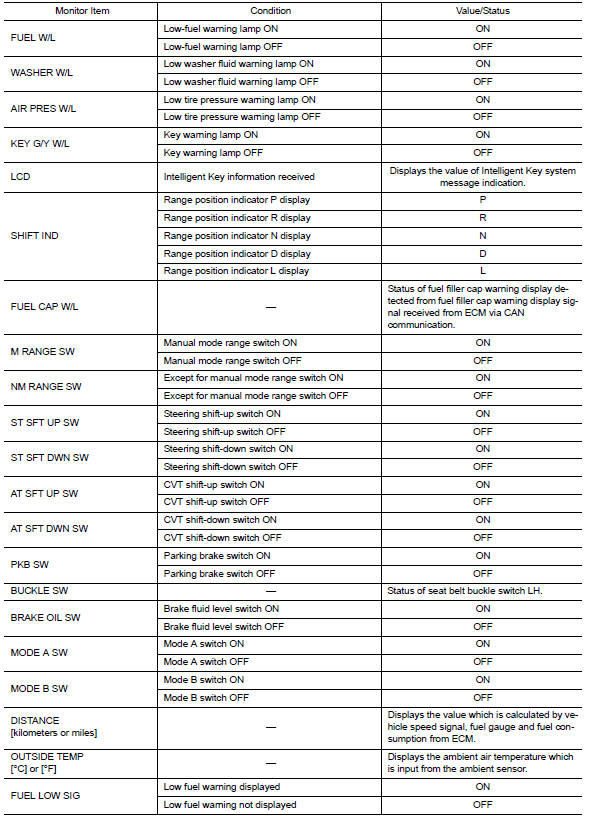
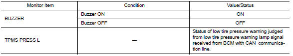
Reference Value
VALUES ON THE DIAGNOSIS TOOL
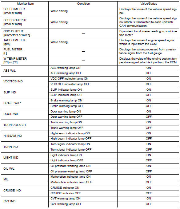
NOTE:
* The monitor will indicate "OFF" even though the brake warning lamp is on if either of the following conditions exist:
-
The parking brake is engaged
-
The brake fluid level is low
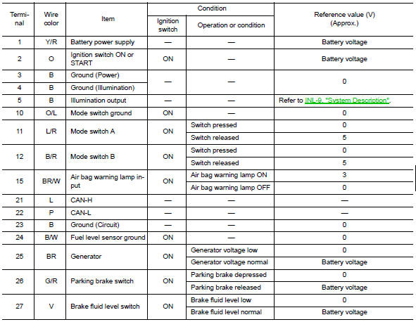
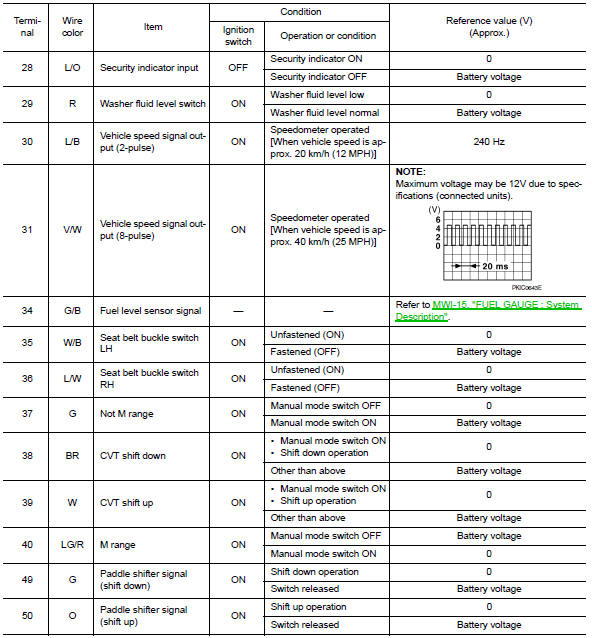
TERMINAL LAYOUT
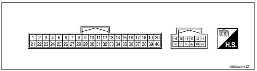
PHYSICAL VALUES
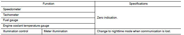
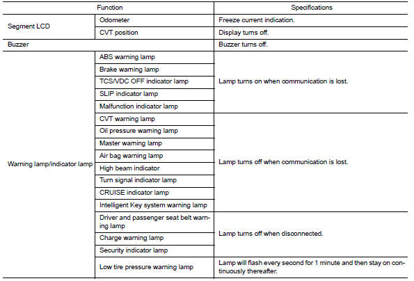
Fail Safe
The combination meter performs a fail-safe operation for the functions listed below when communication is lost.
DTC Index
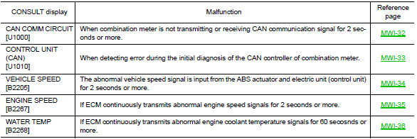
NOTE:
"TIME" indicates the following.
-
0: Indicates that a malfunction is detected at present.
-
1-63: Indicates that a malfunction was detected in the past. (Displays number of ignition switch OFF → ON cycles after malfunction is detected. Self-diagnosis result is erased when "63" is exceeded.)

 BCM (body control module)
Reference Value
NOTE:
The Signal Tech II Tool (J-50190) can be used
to perform the following functions. Refer to the Signal Tech II
User Guide for additional information.
Activate and dis ...
Other materials:
Door mirror
Wiring Diagram - Without Automatic Drive Positioner
...
AV control unit
Removal and Installation
AV control unit
AV control unit bracket (LH)
AV control unit bracket (RH)
A/C auto amp.
Cluster lid C (with A/C and AV switch
assembly attached)
Clip
AV CONTROL UNIT
Removal
CAUTION:
Before replacing AV control unit, perform "READ CONFIGURATI ...
Rear seat
Exploded View - Fixed Seatback
Headrest
Headrest holder (free)
Headrest holder (locked)
Bumper
Seatback assembly
Seatback trim
Seatback pad
Seat cushion trim
Seat cushion pad
Seat cushion wire cover
Seat cushion lock
Seat cushion assembly
Exploded View - 60:40 ...
Nissan Maxima Owners Manual
- Illustrated table of contents
- Safety-Seats, seat belts and supplemental restraint system
- Instruments and controls
- Pre-driving checks and adjustments
- Monitor, climate, audio, phone and voice recognition systems
- Starting and driving
- In case of emergency
- Appearance and care
- Do-it-yourself
- Maintenance and schedules
- Technical and consumer information
Nissan Maxima Service and Repair Manual

0.0052