Nissan Maxima Service and Repair Manual: Hazard switch
Component Function Check
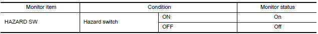
1.CHECK HAZARD SWITCH SIGNAL BY CONSULT
CONSULT DATA MONITOR
- Turn ignition switch ON.
- Select "HAZARD SW" of BCM (FLASHER) DATA MONITOR item.
- With operating the hazard switch, check the monitor status.
Diagnosis Procedure
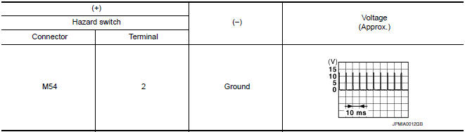
1.CHECK HAZARD SWITCH SIGNAL INPUT
- Turn ignition switch OFF.
- Disconnect hazard switch connector.
- Turn ignition switch ON.
- Check voltage between hazard switch harness connector and ground.
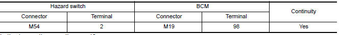
2.CHECK HAZARD SWITCH SIGNAL OPEN CIRCUIT
- Turn ignition switch OFF.
- Disconnect BCM connector M19.
- Check continuity between hazard harness connector and BCM harness connector
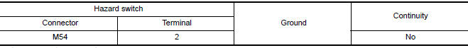
3.CHECK HAZARD SWITCH SIGNAL SHORT CIRCUIT
Check continuity between hazard switch harness connector and ground.
4.CHECK HAZARD SWITCH GROUND OPEN CIRCUIT
Check continuity between hazard switch harness connector and ground.

 Optical sensor
Description
The optical sensor converts the outside brightness (lux) to voltage and
transmits the optical sensor signal to the BCM.
Component Function Check
1.CHECK OPTICAL SENSOR SIGNAL BY CONSU ...

Other materials:
Periodic maintenance
ENGINE COOLANT
System Inspection
WARNING:
Do not remove the radiator cap when the engine is hot. Serious burns could occur
from high pressure
coolant escaping from the radiator. Wrap a thick cloth around the radiator cap.
Slowly turn it a quarter
turn to allow built-up pressure to escape. C ...
Service data and specifications (SDS)
Oil Pressure
Regulator Valve
Oil Pump
Oil Capacity
...
BSW system limitations
WARNING
Listed below are the system limitations for
the BSW system. Failure to operate the
vehicle in accordance with these system
limitations could result in serious injury or
death.
The BSW system cannot detect all vehicles
under all conditions.
The radar sensors may not be able to
detect ...
Nissan Maxima Owners Manual
- Illustrated table of contents
- Safety-Seats, seat belts and supplemental restraint system
- Instruments and controls
- Pre-driving checks and adjustments
- Monitor, climate, audio, phone and voice recognition systems
- Starting and driving
- In case of emergency
- Appearance and care
- Do-it-yourself
- Maintenance and schedules
- Technical and consumer information
Nissan Maxima Service and Repair Manual

0.0071