Nissan Maxima Service and Repair Manual: Headlining
Exploded View
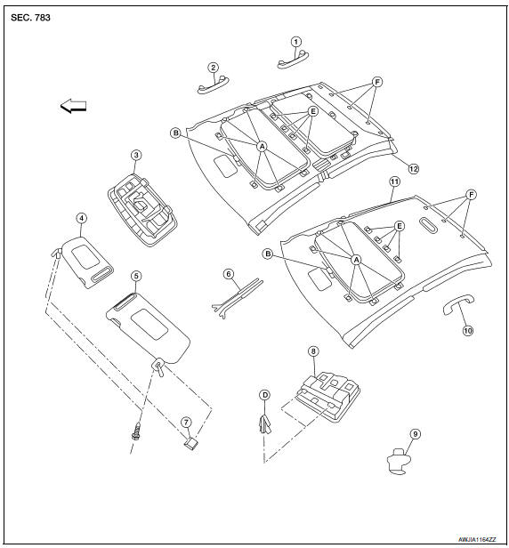
- Rear assist grip
- Front assist grip
- Front room/map lamp assembly (dual panel- sunroof)
- Sun visor (RH)
- Sun visor (LH)
- Mirror harness cover
- Sun visor cover
- Front room/map lamp assembly
- Sun visor holder
- Rear assist grip LH
- Headlining assembly (single panel sunroof)
- Headlining assembly (dual panel-sunroof)
- Dual lock fastener
- Sunroof clip
- Screw
- Metal clip
- Magnets
- Clip
 Front
Front
Removal and Installation
CAUTION:
- - Disconnect the negative and positive battery terminals and wait at least three minutes.
- Be careful not to bend or crease the headlining during removal or installation
REMOVAL
- Recline the front seats to the fully reclined position.
- Disconnect the negative and positive battery terminals. Refer to PG-67, "Removal and Installation (Battery)".
- Remove front pillar finishers (RH/LH). Refer to INT-24, "Removal and Installation".
- Disconnect headlining harness and antenna feeder connectors.
- Remove center pillar upper finishers (RH/LH). Refer to INT-24, "Removal and Installation".
- Remove rear pillar finishers (RH/LH). Refer to INT-24, "Removal and Installation".
- Disconnect antenna amplifier and rear window defogger harness connectors.
- Release the molded clip, then remove front and rear assist grips
- Remove the rear view mirror. Refer to MIR-19, "Removal and Installation".
- Remove the sun visors (RH/LH).
- Remove the sun visor covers and screws.
- Disconnect the connector and remove each of the sun visors.
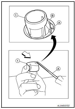
- Insert a suitable thin tool (A) at approximately a 30 degree angle into the sun visor holder notch on the front of the sun visor holder (1) and press in the locking tab (B) to release it. While holding in lock tab (B), turn the sun visor holder (1) 90 degrees to release it from the headliner.
- If the sun visor holder (1) does not fully rotate, make sure that the suitable thin tool (A) is pressing in on the locking tab (B) and is not positioned under locking tab (B). Reinsert the suitable thin tool (A) as necessary to release the locking tab (B).
 : Front
CAUTION: Do not force the sun visor holder when removing as the locking tab may be damaged if the suitable thin tool is not positioned correctly.
- Remove front room/map lamp assembly. Refer to INL-84, "Removal and Installation".
- Release dual lock fasteners around the sunroof opening and the magnets
in the center of the headlining.
Release the sunroof clip using a suitable tool.
- Release the hidden clips near the rear edge of headlining using a suitable tool.
- Drop headlining down and carefully rotate into position. Remove headlining through rear door opening.
CAUTION:
- When removing, two workers are required (one for each front and rear of headlining).
- Cover center console finisher upper surface with a shop cloth to prevent damage.
- The following components are integral to the headlining and are repaired only as an assembly:
- Personal lamps (LH/RH).
- Roof harness assembly.
- Antenna feeder assembly.
- Dual lock attachments
- Magnets
INSTALLATION
Installation is in the reverse order of removal.
 Floor trim
Exploded View
Spacer (RH)
Spacer (LH)
Floor mat hook
Floor carpet
Harness clamp Front
Removal and Installation
REMOVAL
Disconnect the negative and positive battery terminals ...
 Trunk room trim & trunk lid finisher
Exploded View
Trunk forward carpet (if equipped)
Upper trunk finisher
Trunk side finisher (LH)
Trunk net side
Trunk floor carpet
Spacer
Spare tire cover
Trunk net rear (if equi ...
Other materials:
Driver side door mirror defogger does not operate
Diagnosis Procedure
1. CHECK DOOR MIRROR DEFOGGER LH
Check door mirror defogger LH.
PASSENGER SIDE DOOR MIRROR DEFOGGER DOES NOT OPERATE
Diagnosis Procedure
1. CHECK DOOR MIRROR DEFOGGER RH
Check door mirror defogger RH.
REAR WINDOW DEFOGGER SWITCH DOES NOT LIGHT, BUT REAR WINDOW
DEFOGGER O ...
Front door speaker
Description
The audio unit sends audio signals to the BOSE speaker amp. The BOSE speaker
amp. amplifies the audio signals before sending them to the front door
speakers using the audio signal circuits.
Diagnosis Procedure
1.CONNECTOR CHECK
Check the audio unit, BOSE speaker amp. and speaker ...
Combination meter
Reference Value
VALUES ON THE DIAGNOSIS TOOL
NOTE:
* The monitor will indicate "OFF" even though
the brake warning lamp is on if either of the following conditions exist:
The parking brake is engaged
The brake fluid level is low
TERMINAL LAYOUT
PHYSICAL VALUES
...
Nissan Maxima Owners Manual
- Illustrated table of contents
- Safety-Seats, seat belts and supplemental restraint system
- Instruments and controls
- Pre-driving checks and adjustments
- Monitor, climate, audio, phone and voice recognition systems
- Starting and driving
- In case of emergency
- Appearance and care
- Do-it-yourself
- Maintenance and schedules
- Technical and consumer information
Nissan Maxima Service and Repair Manual

0.0072