Nissan Maxima Service and Repair Manual: System description
HEATED STEERING WHEEL
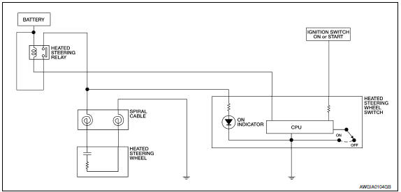
System Diagram

System Description
The heated steering wheel switch controls the heated steering relay. When the switch is turned on, the relay is energized and the heated steering system will operate. The heated steering system will turn off when the steering wheel temperature reaches approximately 86 F (30 C). Heated steering system operation can also be canceled by pressing the heated steering wheel switch again.
NOTE: If the surface temperature of the steering wheel is below 68 F (20 C), the system will heat the steering wheel and cycle off and on to maintain a temperature above 68 F (20 C). The indicator light will remain on as long as the system is on. Push the switch again to turn the heated steering wheel system off manually. The indicator light will go off.
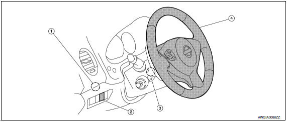
Component Parts Location

- Heated steering relay M97
- Heated steering wheel switch M96
- Spiral cable M26
- Heated steering wheel M114
Component Description

 Steering system
...
 Wiring diagram
HEATED STEERING WHEEL
Wiring Diagram
...
Other materials:
Disk eject signal circuit
Description
The eject signal is output to AV control unit when the eject switch of A/C
and AV switch assembly is pressed.
Diagnosis Procedure
1.CHECK CONTINUITY DISK EJECT SIGNAL CIRCUIT
Turn ignition switch OFF.
Disconnect A/C and AV switch assembly connector M98 and AV
control un ...
Basic inspection
COLLISION DIAGNOSIS
FOR USA AND CANADA
FOR USA AND CANADA : For Frontal Collision
FOR FRONTAL COLLISION: When SRS is activated in a collision
CAUTION: Due to varying models and option
levels, not all parts listed in the chart below apply to all vehicles.
WORK PROCEDURE
Before performing a ...
Secondary speed sensor
Exploded View
Secondary speed sensor
Shim
Transaxle assembly
O-ring
Apply CVT Fluid NS-2
Removal and Installation
REMOVAL
Disconnect the battery negative terminal. Refer
to PG-67, "Removal and Installation (Battery)" ...
Nissan Maxima Owners Manual
- Illustrated table of contents
- Safety-Seats, seat belts and supplemental restraint system
- Instruments and controls
- Pre-driving checks and adjustments
- Monitor, climate, audio, phone and voice recognition systems
- Starting and driving
- In case of emergency
- Appearance and care
- Do-it-yourself
- Maintenance and schedules
- Technical and consumer information
Nissan Maxima Service and Repair Manual
0.005
