Nissan Maxima Service and Repair Manual: Basic inspection
COLLISION DIAGNOSIS
FOR USA AND CANADA
FOR USA AND CANADA : For Frontal Collision
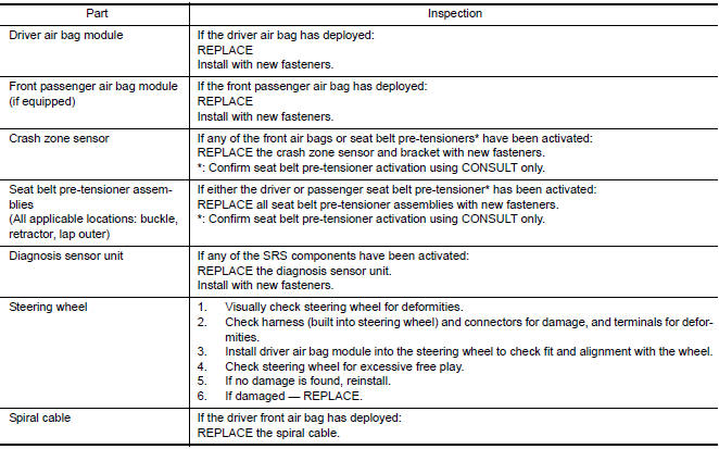
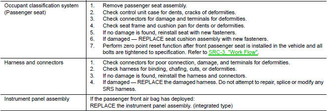
FOR FRONTAL COLLISION: When SRS is activated in a collision
CAUTION: Due to varying models and option levels, not all parts listed in the chart below apply to all vehicles.
WORK PROCEDURE
- Before performing any of the following steps, ensure that all vehicle body and structural repairs have been completed.
- Replace the diagnosis sensor unit.
- Remove the front air bag modules, crash zone sensor assembly, bracket and seat belt pre-tensioner assemblies.
- Check the SRS components using the table below: Replace any SRS components showing visible signs of damage. (dents, cracks and deformation, etc.)
- Install new front air bag modules, crash zone sensor assembly, bracket and seat belt pre-tensioner assemblies.
- Perform self-diagnosis using CONSULT or air bag warning lamp.
Refer to SRC-14, "Self-Diagnosis Function (Without CONSULT)" for details.
Ensure entire SRS operates properly.
- After the work is completed, perform self-diagnosis to check that no malfunction is detected. Refer to SRC-12, "SRS Operation Check".
SRS INSPECTION (FOR FRONTAL COLLISION)
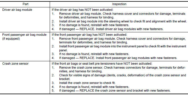
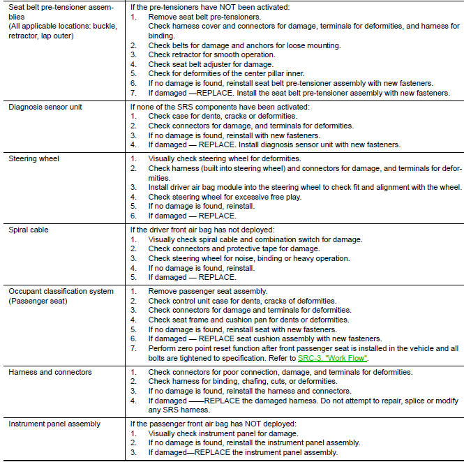
FOR FRONTAL COLLISION: When SRS is not activated in a collision
CAUTION: Due to varying models and option levels, not all parts listed in the chart below apply to all vehicles.
WORK PROCEDURE
- Before performing any of the following steps, ensure that all vehicle body and structural repairs have been completed.
- Check the SRS components using the table below: Replace any SRS components showing visible signs of damage. (dents, cracks and deformation, etc.)
- Perform self-diagnosis using CONSULT or air bag warning lamp.
Refer to SRC-14, "Self-Diagnosis Function (Without CONSULT)" for details.
Ensure entire SRS operates properly.
- After the work is completed, perform self-diagnosis to check that no malfunction is detected. Refer to SRC-12, "SRS Operation Check".
SRS INSPECTION (FOR FRONTAL COLLISION)
FOR USA AND CANADA : For Side and Rollover Collision
FOR SIDE AND ROLLOVER COLLISION: When SRS is activated in a collision
CAUTION: Due to varying models and option levels, not all parts listed in the chart below apply to all vehicles.
WORK PROCEDURE
- Before performing any of the following steps, ensure that all vehicle body and structural repairs have been completed.
- Replace the following components:
- Front seat back assembly (on the side on which side air bag is activated).
- Door finisher (on the side on which door-mounted curtain air bag is activated).
- Pop-up roll bar assemblies and pop-up roll bar covers.
- Side air bag (satellite) sensor LH/RH (on the side on which side air bag is activated).
- Diagnosis sensor unit.
- Seat belt pre-tensioner assemblies.
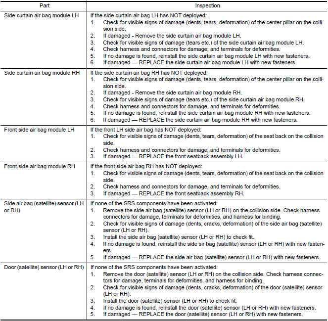
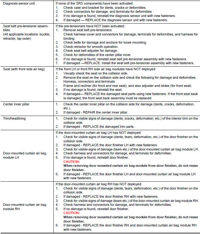
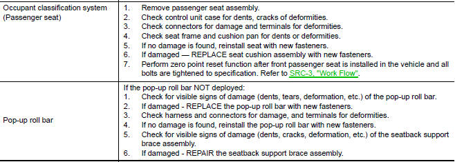
- Check the SRS components and the related parts using the following
table.
Replace any SRS components and the related parts showing visible signs of damage (dents, cracks, deformation, etc.).
- Perform self-diagnosis using CONSULT and "AIR BAG" warning lamp. Refer to SRC-12, "SRS Operation Check" for details. Make sure entire SRS operates properly.
- After the work is completed, perform self-diagnosis to check that no malfunction is detected. Refer to SRC-14, "Trouble Diagnosis without CONSULT".
SRS INSPECTION (FOR SIDE AND ROLLOVER COLLISION)

FOR SIDE AND ROLLOVER COLLISION: When SRS is not activated in a collision
CAUTION: Due to varying models and option levels, not all parts listed in the chart below apply to all vehicles.
WORK PROCEDURE
- Before performing any of the following steps, ensure that all vehicle body and structural repairs have been completed.
- Check the SRS components and the related parts using the following table.
- If the front seat back assembly is damaged, the front seat back assembly must be replaced.
- If the door finisher assembly is damaged, the door finisher assembly and door-mounted curtain air bag module must be replaced.
- Perform self-diagnosis using CONSULT and "AIR BAG" warning lamp. Refer to SRC-12, "SRS Operation Check" for details. Make sure entire SRS operates properly.
- After the work is completed, perform self-diagnosis to check that no malfunction is detected. Refer to SRC-14, "Trouble Diagnosis without CONSULT".
SRS INSPECTION (FOR SIDE AND ROLLOVER COLLISION)
 Preparation
Special Service Tool
The actual shapes of the tools may differ from those illustrated here.
...

Other materials:
Chassis and body maintenance
IN-CABIN MICROFILTER
IN-CABIN MICROFILTER : Removal and Installation
REMOVAL
Disengage the filter cover tab (1) by pushing up and pull out to
remove the filter cover.
Remove the in-cabin microfilter from the blower unit.
INSTALLATION
Installation is in the reverse order of removal ...
IPDM E/R (intelligent power distribution module engine room)
Reference Value
VALUES ON THE DIAGNOSIS TOOL
TERMINAL LAYOUT
PHYSICAL VALUES
Fail Safe
CAN COMMUNICATION CONTROL
When CAN communication with ECM and BCM is impossible, IPDM E/R performs
fail-safe control. After CAN communication recovers normally, it also returns
to nor ...
P0172, P0175 fuel injection system function
DTC Logic
DTC DETECTION LOGIC
With the Air/Fuel Mixture Ratio Self-Learning Control, the actual mixture
ratio can be brought closely to the
theoretical mixture ratio based on the mixture ratio feedback signal from A/F
sensor 1. The ECM calculates
the necessary compensation to correct the o ...
Nissan Maxima Owners Manual
- Illustrated table of contents
- Safety-Seats, seat belts and supplemental restraint system
- Instruments and controls
- Pre-driving checks and adjustments
- Monitor, climate, audio, phone and voice recognition systems
- Starting and driving
- In case of emergency
- Appearance and care
- Do-it-yourself
- Maintenance and schedules
- Technical and consumer information
Nissan Maxima Service and Repair Manual

0.007