Nissan Maxima Service and Repair Manual: Rear window defogger system
System Diagram
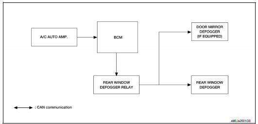
System Description
Operation Description
- When rear window defogger switch is turned ON while ignition switch is ON, the A/C auto amp. (rear window defogger switch) transmits rear window defogger switch signal to BCM.
- BCM turns rear window defogger relay ON when rear window defogger switch signal is received.
- Rear window defogger and door mirror defogger (with door mirror defogger) are supplied with power and operate when rear window defogger relay turns ON.
- Rear window defogger ON is displayed when controller (A/C auto amp.) receives signals.
Timer function
- BCM turns rear window defogger relay ON for approximately 15 minutes when rear window defogger switch is turned ON while ignition switch is ON. It makes rear window defogger and door mirror defogger (with door mirror defogger) operate.
- Timer is canceled after pressing rear window defogger switch again during timer operation. Then BCM turns rear window defogger relay OFF. The same reaction also occurs during timer operation, if the ignition switch is turned OFF.
INPUT/OUTPUT SIGNAL CHART
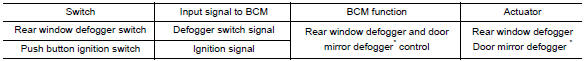
*: With door mirror defogger
Component Parts Location
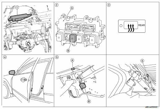
- BCM M16, M17, M18, M19 (view with instrument panel removed)
- A. Fuse block (J/B)
B. Rear window defogger relay J-2 - A/C auto amp. (rear window defogger switch) M37
- Door mirror (door mirror defogger) LH D4, RH D107 (if equipped)
- A. Rear window defogger B53
B. Condenser B52 (view with rear pillar finisher LH removed) - Rear window defogger B54 (view with rear pillar finisher RH removed)
Component Description
| BCM |
|
| Rear window defogger relay |
|
| A/C auto amp. (rear window defogger switch) |
|
| Rear window defogger |
|
| Door mirror defogger* |
|
*: With heated mirrors

 Diagnosis system (BCM)
COMMON ITEM
COMMON ITEM: CONSULT Function (BCM - COMMON ITEM)
APPLICATION ITEM
CONSULT performs the following functions via CAN communication with BCM.
Direct Diagnostic Mode
Des ...
Other materials:
TCS
System Diagram
System Description
Traction Control System is a function that electronically controls
engine torque and brake fluid pressure to
ensure the optimum slippage ratio at drive wheels by computing wheel speed
signals from 4 wheel sensors.
When ABS actuator and electric u ...
IPDM E/R (intelligent power distribution module engine room)
Reference Value
VALUES ON THE DIAGNOSIS TOOL
TERMINAL LAYOUT
PHYSICAL VALUES
Fail Safe
CAN COMMUNICATION CONTROL
When CAN communication with ECM and BCM is impossible, IPDM E/R performs
fail-safe control. After CANcommunication recovers normally, it also returns
to norm ...
P1564 ASCD steering switch
Description
ASCD steering switch has variant values of electrical resistance for each
button. ECM reads voltage variation
of switch, and determines which button is operated.
Refer to EC-68, "System Diagram" for the ASCD function.
DTC Logic
DTC DETECTION LOGIC
NOTE:
If DTC P156 ...
Nissan Maxima Owners Manual
- Illustrated table of contents
- Safety-Seats, seat belts and supplemental restraint system
- Instruments and controls
- Pre-driving checks and adjustments
- Monitor, climate, audio, phone and voice recognition systems
- Starting and driving
- In case of emergency
- Appearance and care
- Do-it-yourself
- Maintenance and schedules
- Technical and consumer information
Nissan Maxima Service and Repair Manual

0.0063