Nissan Maxima Service and Repair Manual: Auto light system
Nissan Maxima Service and Repair Manual / Driver controls / Exterior lighting system / Wiring diagram / Auto light system
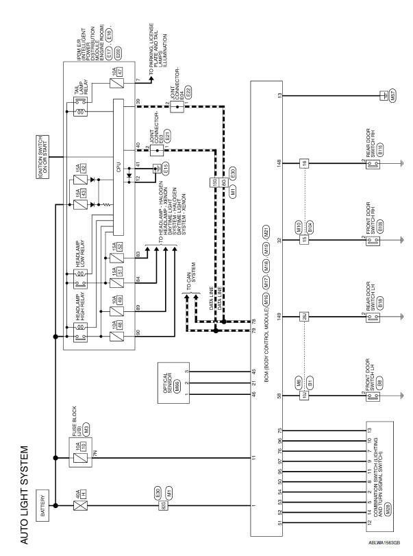
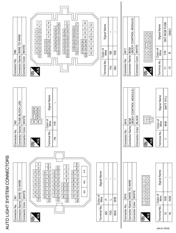
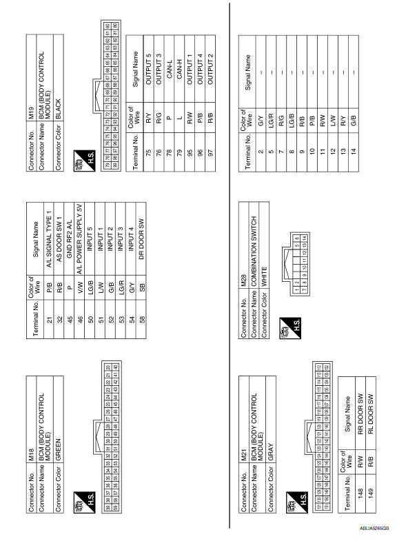
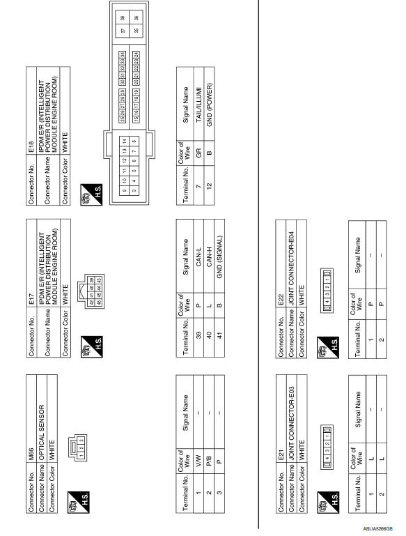
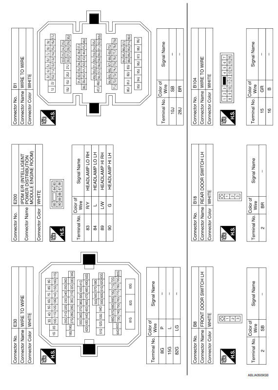
Wiring Diagram
 Daytime running light system
Wiring Diagram
...
 Front fog lamp system
Wiring Diagram
...
Other materials:
RGB (B: blue) signal circuit
Description
Transmit the image displayed with AV control unit with RGB signal to the
display unit.
Diagnosis Procedure
1.CHECK CONTINUITY RGB (B: BLUE) SIGNAL CIRCUIT
Turn ignition switch OFF.
Disconnect display unit connector M141 and AV control unit
connector M117.
Check contin ...
Stop lamp
Wiring Diagram
...
Wiring diagram
MONOCHROME DISPLAY
Wiring Diagram - With BOSE Audio System
...
Nissan Maxima Owners Manual
- Illustrated table of contents
- Safety-Seats, seat belts and supplemental restraint system
- Instruments and controls
- Pre-driving checks and adjustments
- Monitor, climate, audio, phone and voice recognition systems
- Starting and driving
- In case of emergency
- Appearance and care
- Do-it-yourself
- Maintenance and schedules
- Technical and consumer information
Nissan Maxima Service and Repair Manual

© 2017-2026 Copyright www.nimainfo.com
0.0077
0.0077