Nissan Maxima Service and Repair Manual: Wiring diagram
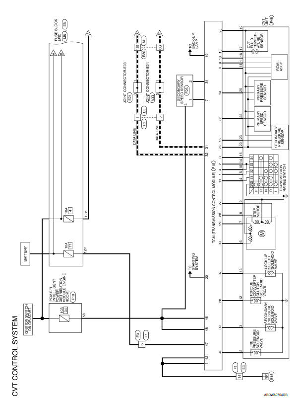
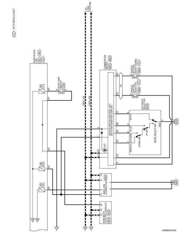
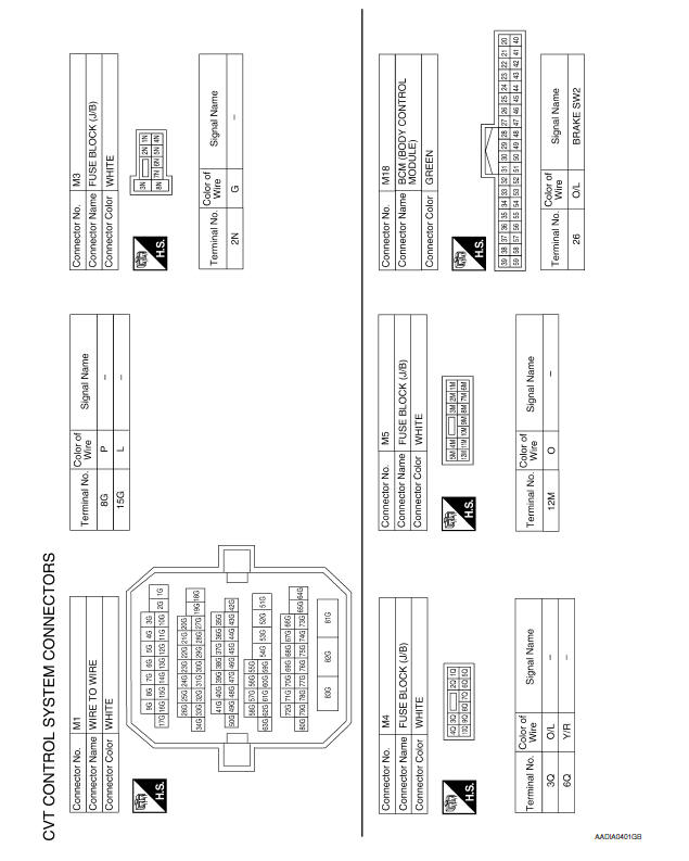
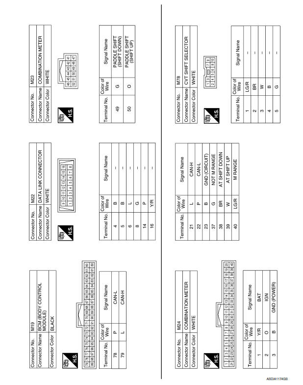
CVT CONTROL SYSTEM
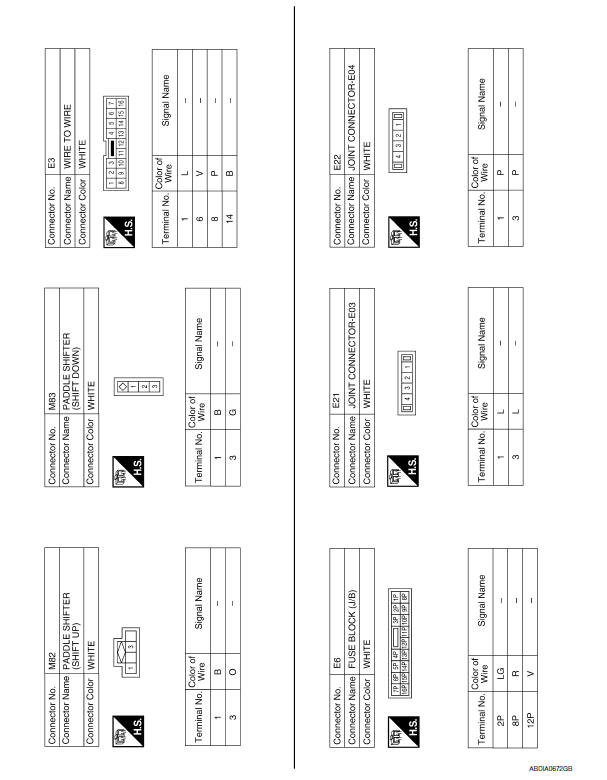
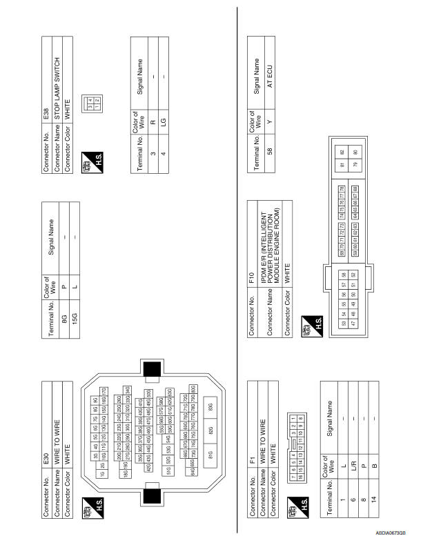
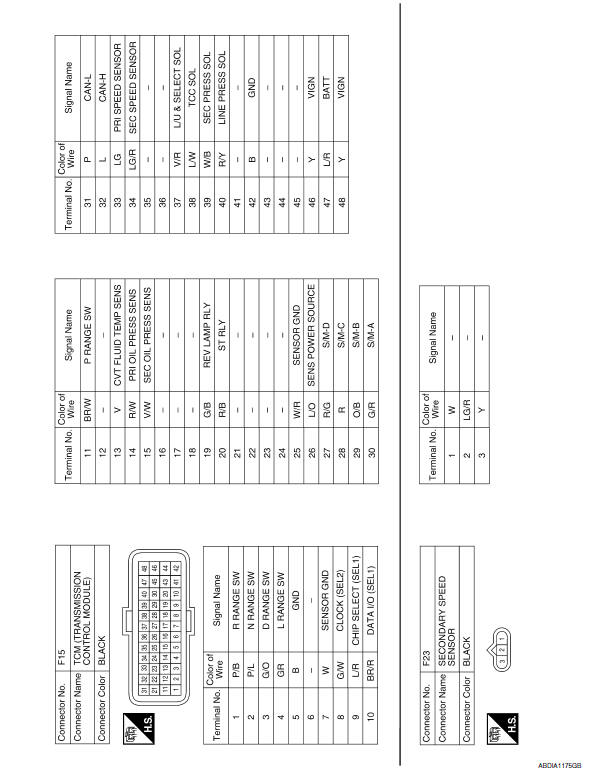
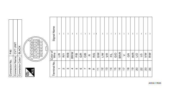
Wiring Diagram
 ECU diagnosis information
TCM
Reference Value
VALUES ON THE DIAGNOSIS TOOL
TERMINAL LAYOUT
PHYSICAL VALUES
Fail-safe
The TCM has an electrical fail-safe mode. In this mode
TCM operates even if there is an ...
 CVT shift lock system
Wiring Diagram
...
Other materials:
B2636, B2637, B2638, B2639, B2654, B2655 mode door motor
Description
COMPONENT DESCRIPTION
Mode Door Motor
The mode door motor (1) is attached to the heater & cooling unit
assembly.
It rotates so that air is discharged from the outlet set by the
A/C
auto amp. Motor rotation is conveyed to a link which activates the
mode door.
D ...
DTC B2205 vehicle speed circuit
Description
The ABS actuator and electric unit (control unit) provides a vehicle speed
signal to the combination meter via
CAN communication lines.
DTC Logic
Diagnosis Procedure
Symptom: Displays "VEHICLE SPEED CIRC [B2205]" as a self-diagnosis result of
combination meter.
1.CHECK COMBI ...
Automatic door locks
System Diagram
System Description
DOOR LOCK FUNCTION
The door lock and unlock switch (driver side) is build into power
window main switch.
The door lock and unlock switch (passenger side) is on door trim.
Interlocked with the locking operation of door lock and unlock
switch ...
Nissan Maxima Owners Manual
- Illustrated table of contents
- Safety-Seats, seat belts and supplemental restraint system
- Instruments and controls
- Pre-driving checks and adjustments
- Monitor, climate, audio, phone and voice recognition systems
- Starting and driving
- In case of emergency
- Appearance and care
- Do-it-yourself
- Maintenance and schedules
- Technical and consumer information
Nissan Maxima Service and Repair Manual

0.0054