Nissan Maxima Service and Repair Manual: CVT shift lock system
Nissan Maxima Service and Repair Manual / Transmission & driveline / Transaxle & transmission / CVT shift lock system
Wiring Diagram
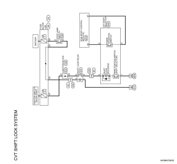
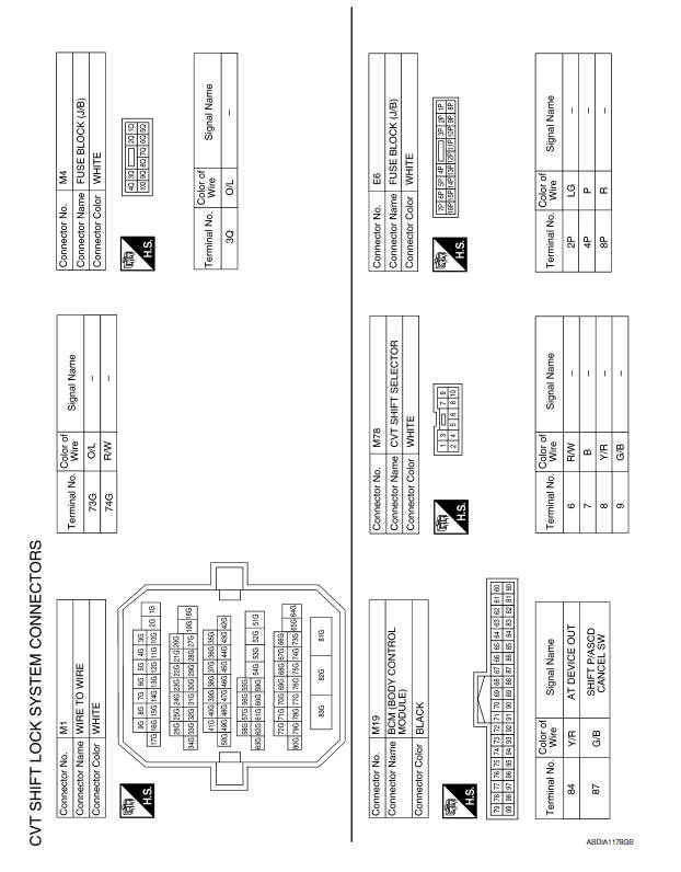
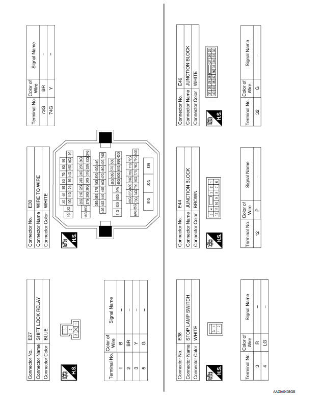
 Wiring diagram
CVT CONTROL SYSTEM
Wiring Diagram
...
 Symptom diagnosis
SYSTEM SYMPTOM
Symptom Table
The diagnostics item numbers show the sequence for
inspection. Inspect in order from item 1.
...
Other materials:
Engine compartment
WARNING
Never use a fuse of a higher or lower
amperage rating than specified on the
fuse box cover. This could damage the
electrical system or electronic control
units or cause a fire.
If any electrical equipment does not come on,
check for an open fuse.
1. Be sure the ignition switch ...
Precaution
Precaution for Supplemental Restraint System (SRS) "AIR BAG" and
"SEAT BELT PRE-TENSIONER"
The Supplemental Restraint System such as "AIR BAG" and "SEAT BELT
PRE-TENSIONER", used along with a front seat belt, helps to reduce the risk
or severity of injury to the driver and front passenger for ...
Stop lamp
Wiring Diagram
...
Nissan Maxima Owners Manual
- Illustrated table of contents
- Safety-Seats, seat belts and supplemental restraint system
- Instruments and controls
- Pre-driving checks and adjustments
- Monitor, climate, audio, phone and voice recognition systems
- Starting and driving
- In case of emergency
- Appearance and care
- Do-it-yourself
- Maintenance and schedules
- Technical and consumer information
Nissan Maxima Service and Repair Manual

© 2017-2026 Copyright www.nimainfo.com
0.0059
0.0059