Nissan Maxima Service and Repair Manual: Cooling system
Cooling Circuit
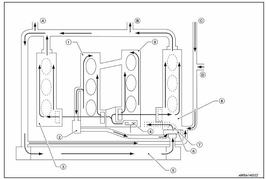
- Cylinder block (RH)
- Oil cooler
- Cylinder head (RH)
- Water pump
- Radiator
- Water inlet
- Thermostat
- Cylinder head (LH)
- Cylinder block (LH)
- To heater
- To electric throttle control actuator
- From heater
- From electric throttle control actuator
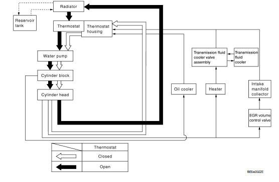
Schematic
 Overheating cause analysis
Troubleshooting Chart
...
 Periodic maintenance
ENGINE COOLANT
System Inspection
WARNING:
Do not remove the radiator cap when the engine is hot. Serious burns could occur
from high pressure
coolant escaping from the radiator. Wrap a thick clo ...
Other materials:
Headlamp
System Diagram
System Description
Control of the headlamp system is dependent upon the position of the
combination switch (lighting and turn signal switch). When the lighting
switch is placed in the 2nd position, the BCM (body control module) receives
input requesting the headlamps and par ...
Refrigerant pressure sensor
Description
The refrigerant pressure sensor is installed at the condenser of the air
conditioner system. The sensor uses an
electrostatic volume pressure transducer to convert refrigerant pressure to
voltage. The voltage signal is sent
to ECM, and ECM controls cooling fan system.
Compo ...
Diagnosis system (BCM)
COMMON ITEM
COMMON ITEM : CONSULT Function (BCM - COMMON ITEM)
APPLICATION ITEM
CONSULT performs the following functions via CAN communication with BCM.
SYSTEM APPLICATION
BCM can perform the following functions.
BCM
BCM : CONSULT Function (BCM - BCM)
ECU IDENTIFICATION
The BCM part ...
Nissan Maxima Owners Manual
- Illustrated table of contents
- Safety-Seats, seat belts and supplemental restraint system
- Instruments and controls
- Pre-driving checks and adjustments
- Monitor, climate, audio, phone and voice recognition systems
- Starting and driving
- In case of emergency
- Appearance and care
- Do-it-yourself
- Maintenance and schedules
- Technical and consumer information
Nissan Maxima Service and Repair Manual

0.0054