Nissan Maxima Service and Repair Manual: Power supply and ground circuit
BCM
BCM : Diagnosis Proce
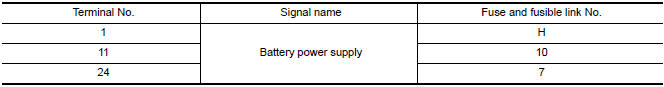
1. CHECK FUSE AND FUSIBLE LINK
Check if the following BCM fuses or fusible link are blow
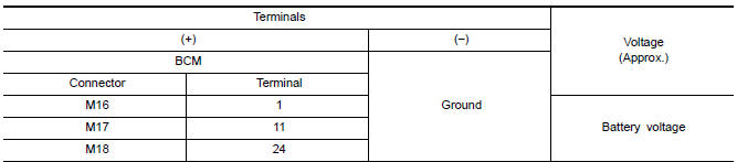
2. CHECK POWER SUPPLY CIRCUIT
- Turn ignition switch OFF.
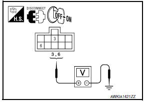
- Disconnect BCM.
- Check voltage between BCM harness connector and ground.
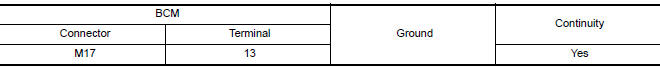
3. CHECK GROUND CIRCUIT
Check continuity between BCM harness connector and ground.
SUNROOF MOTOR ASSEMBLY
SUNROOF MOTOR ASSEMBLY : Diagnosis Procedure
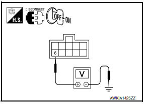
1.CHECK POWER SUPPLY
- Turn ignition switch OFF.
- Disconnect sunroof motor assembly connector.
- Turn ignition switch ON.
- Check voltage between sunroof motor assembly harness connector and ground.
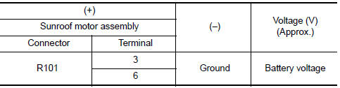
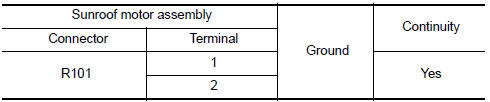
2.CHECK GROUND CIRCUIT
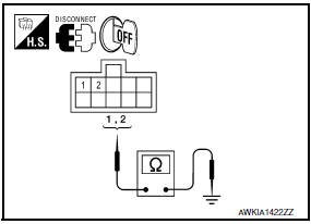
- Turn ignition switch OFF.
- Check continuity between sunroof motor assembly harness connector and ground.
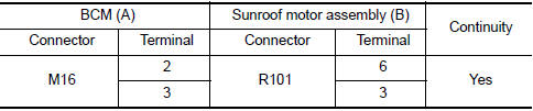
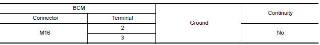
3.CHECK SUNROOF MOTOR CIRCUIT
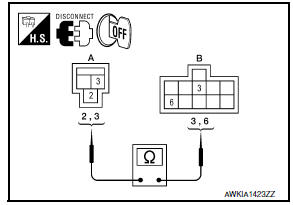
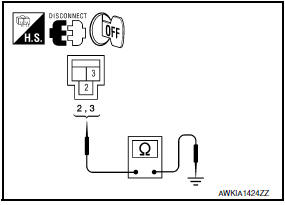
- Turn ignition switch OFF.
- Disconnect BCM connector.
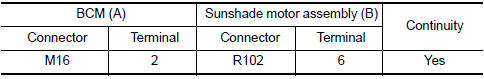
- Check continuity between BCM harness connector (A) and sunroof motor assembly harness connector (B).
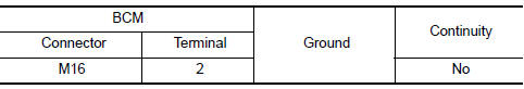
- Check continuity between BCM harness connector and ground.
4.CHECK INTERMITTENT INCIDENT
SUNSHADE MOTOR ASSEMBLY
SUNSHADE MOTOR ASSEMBLY : Diagnosis Procedure
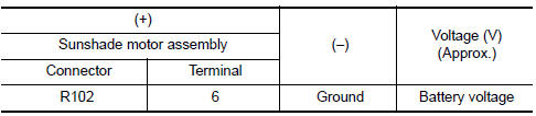
1.CHECK POWER SUPPLY
- Turn ignition switch OFF.
- Disconnect sunshade motor assembly connector.
- Turn ignition switch ON.
- Check voltage between sunshade motor assembly harness connector and ground.
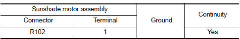
2.CHECK GROUND CIRCUIT
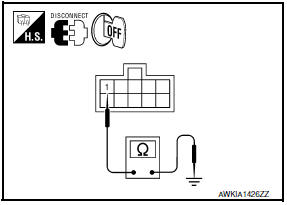
- Turn ignition switch OFF.
- Check continuity between sunshade motor assembly harness connector and ground.
3.CHECK SUNSHADE MOTOR CIRCUIT
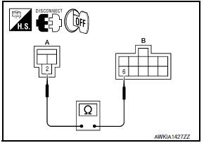
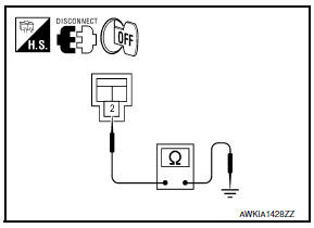
- Turn ignition switch OFF.
- Disconnect BCM connector.
- Check continuity between BCM harness connector (A) and sunshade motor assembly harness connector (B).
- Check continuity between BCM harness connector and ground.
4.CHECK INTERMITTENT INCIDENT

 Communication signal circuit
Description
Detects door open/close condition.
Diagnosis Procedure
1.CHECK FRONT DOOR SWITCH INPUT SIGNAL
Turn ignition switch OFF.
Disconnect sunshade motor assembly connector.
Turn igniti ...
Other materials:
AV control unit
Reference Value
VALUES ON THE DIAGNOSIS TOOL
CONSULT data monitor item
TERMINAL LAYOUT
PHYSICAL VALUES
*1 With satellite radio
DTC Index
Self-diagnosis results display item
...
B2602 shift position
Description
BCM confirms the shift position with the following 2
signals.
CVT selector lever
Speed signal from meter
DTC Logic
DTC DETECTION LOGIC
NOTE:
If DTC B2602 is displayed with DTC
U1000, first perform the trouble diagnosis for DTC U1000. Refer ...
Unit disassembly and assembly
COOLING FAN
Disassembly and Assembly of Cooling Fan
Fan blade
Fan shroud
Fan motor
DISASSEMBLY
Remove fan blade nut.
Remove fan blade from fan motor.
Remove fan motor bolts and remove fan motor from fan shroud.
ASSEMBLY
Assembly is in the reverse order of disassembly. ...
Nissan Maxima Owners Manual
- Illustrated table of contents
- Safety-Seats, seat belts and supplemental restraint system
- Instruments and controls
- Pre-driving checks and adjustments
- Monitor, climate, audio, phone and voice recognition systems
- Starting and driving
- In case of emergency
- Appearance and care
- Do-it-yourself
- Maintenance and schedules
- Technical and consumer information
Nissan Maxima Service and Repair Manual

0.0078