Nissan Maxima Service and Repair Manual: Removal and installation
GENERATOR
Exploded View
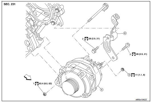
- -3 Tightening order
- Generator
- B terminal nut
- Generator bracket
 Front
Front
Removal and Installation
REMOVAL
- Remove hoodledge covers (LH/RH).
- Remove cooling fan assembly. Refer to CO-16, "Removal and Installation".
- Remove the A/C compressor. Refer to HA-37, "Removal and Installation for Compressor".
- Remove A/C idler pulley EM-15, "Removal and Installation of Drive Belt Auto-tensioner".
- Disconnect the oil pressure switch EM-36, "Exploded View".
- Disconnect the generator harness connectors.
- Remove the generator bolt and nuts, using power tools.
- Remove generator bracket.
- Slide the generator out and remove.
INSTALLATION
Installation is in the reverse order of removal. Refer to CHG-28, "Exploded View"
- Temporarily tighten bolts and nut, then finish tightening in the
specified numerical order.
CAUTION: Be sure to tighten "B" terminal nut carefully. - Install generator and check tension of belt. Refer to EM-14, "Checking Drive Belts".
- For this model, the power generation voltage variable control system that controls the power generation voltage of the generator has been adopted. Therefore, the power generation voltage variable control system operation inspection should be performed after replacing the generator, and then make sure that the system operates normally. Refer to CHG-11, "Diagnosis Procedure".
Inspection
GENERATOR PULLEY INSPECTION
Perform the following.
- Make sure that generator pulley does not rattle.
- Make sure that generator pulley nut is tight.
NOTE: Replace the generator as an assembly if necessary.
 Preparation
PREPARATION
Special Service Tool
The actual shapes of the tools may differ from those illustrated here.
Commercial Service Tool
...
 Service data and specifications (SDS)
SERVICE DATA AND SPECIFICATIONS (SDS)
Generator
*: Always check with the Parts Department for the latest parts information ...
Other materials:
B1023 passenger air bag off indicator
Description
DTC B1023 FRONT PASSENGER AIR BAG OFF INDICATOR
The front passenger air bag off indicator is wired to the air bag diagnosis
sensor unit. The air bag diagnosissensor unit monitors the front passenger
air bag off indicator and circuit for failures.
PART LOCATION
DTC Logic
DTC DETE ...
Oil pump
Removal and Installation
REMOVAL
Remove the engine from the vehicle. Refer to EM-103, "Removal and
Installation".
Remove the upper oil pan. Refer to EM-37, "Removal and
Installation (Upper Oil Pan)".
Remove the timing chain. Refer to EM-64, "Removal and
Installati ...
Control unit
Removal and Installation
A/C AND AV SWITCH ASSEMBLY
Removal and Installation
The A/C and AV switch assembly is located in cluster lid C.
Refer to AV-481, "Removal and Installation" (BOSE W/COLOR
DISPLAY).
Refer to AV-652, "Removal and Installation" (BOSE W/COLOR DISPL ...
Nissan Maxima Owners Manual
- Illustrated table of contents
- Safety-Seats, seat belts and supplemental restraint system
- Instruments and controls
- Pre-driving checks and adjustments
- Monitor, climate, audio, phone and voice recognition systems
- Starting and driving
- In case of emergency
- Appearance and care
- Do-it-yourself
- Maintenance and schedules
- Technical and consumer information
Nissan Maxima Service and Repair Manual

0.0182