Nissan Maxima Service and Repair Manual: Preparation
PREPARATION
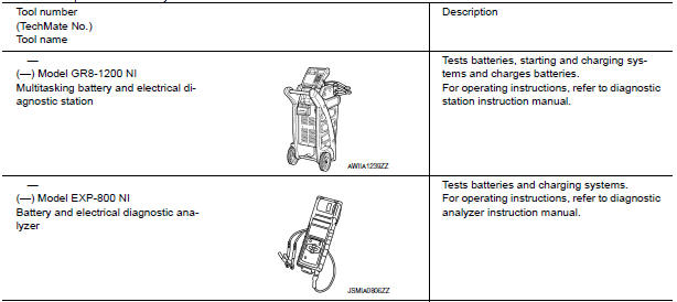
Special Service Tool
The actual shapes of the tools may differ from those illustrated here.
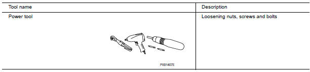
Commercial Service Tool
 Precaution
PRECAUTIONS
Precaution for Supplemental Restraint System (SRS) "AIR BAG" and "SEAT
BELT
PRE-TENSIONER"
The Supplemental Restraint System such as "AIR BAG" and "SEAT BELT PRE- ...
 Removal and installation
GENERATOR
Exploded View
-3 Tightening order
Generator
B terminal nut
Generator bracket
Front
Removal and Installation
REMOVAL
Remove hoodledge covers (LH/RH).
Remove co ...
Other materials:
Precaution
Precaution for Supplemental Restraint System (SRS) "AIR BAG" and
"SEAT BELTPRE-TENSIONER"
The Supplemental Restraint System such as “AIR BAG” and “SEAT BELT
PRE-TENSIONER”, used alongwith a front seat belt, helps to reduce the risk
or severity of injury to the driver and front passeng ...
P1574 ASCD vehicle speed sensor
Description
The ECM receives two vehicle speed signals via the CAN communication line.
One is sent from combination
meter, and the other is from TCM (Transmission control module). The ECM uses
these signals for ASCD control.
Refer to EC-68, "System Diagram" for ASCD functions.
D ...
Diagnosis system (ipdm E/R)
Diagnosis Description
AUTO ACTIVE TEST
Description
In auto active test mode, the IPDM E/R sends a drive signal to the following
systems to check their operation.
Oil pressure warning lamp
Front wiper (LO, HI)
Parking lamps
Side marker lamps
License plate lamps
Tail lamps
Front f ...
Nissan Maxima Owners Manual
- Illustrated table of contents
- Safety-Seats, seat belts and supplemental restraint system
- Instruments and controls
- Pre-driving checks and adjustments
- Monitor, climate, audio, phone and voice recognition systems
- Starting and driving
- In case of emergency
- Appearance and care
- Do-it-yourself
- Maintenance and schedules
- Technical and consumer information
Nissan Maxima Service and Repair Manual

0.0079