Nissan Maxima Service and Repair Manual: Diagnosis and repair work flow
Work Flow
INTRODUCTION
The TCM receives signals from the vehicle speed sensor and transmission range switch. Then it provides shift control or lock-up control via CVT solenoid valves.
The TCM also communicates with the ECM by means of signals sent from sensing elements used with the OBD-related parts of the CVT system for malfunction-diagnostic purposes. The TCM is capable of diagnosing malfunctioning parts while the ECM can store malfunctions in its memory.
Input and output signals must always be correct and stable in the operation of the CVT system. The CVT system must be in good operating condition and be free of valve seizure, solenoid valve malfunction, etc.
It is much more difficult to diagnose a malfunction that occurs intermittently rather than continuously. Most intermittent malfunctions are caused by poor electric connections or improper wiring. In this case, careful checking of suspected circuits may help prevent the replacement of good parts.
A visual check only may not find the cause of the malfunctions. A road test with CONSULT (or GST) or a circuit tester connected should be performed. Follow the "DETAILED FLOW".
Before undertaking actual checks, take a few minutes to talk with a customer who approaches with a driveability complaint. The customer can supply good information about such malfunctions, especially intermittent ones. Find out what symptoms are present and under what conditions they occur. A "Diagnostic Work Sheet" as shown on the example (Refer to TM-6) should be used.
Start your diagnosis by looking for "conventional" malfunctions first.
This will help troubleshoot driveability malfunctions on an electronically controlled engine vehicle.
Also check related Service Bulletins.
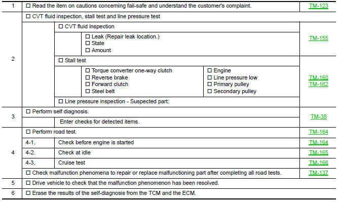
DETAILED FLOW
- COLLECT THE INFORMATION FROM THE CUSTOMER
Get the detailed information from the customer about the symptom (the condition and the environment when the incident/malfunction occurred) using the diagnosis work sheet. Refer to TM-6, "Diagnostic Work Sheet".
2.CHECK SYMPTOM 1
Check the following items based on the information obtained from the customer.
- Fail-safe. Refer to TM-123, "Fail-safe".
- CVT fluid inspection. Refer to TM-155, "Inspection".
- Line pressure test. Refer to TM-162, "Inspection and Judgment".
- Stall test. Refer to TM-160, "Inspection and Judgment".
3.CHECK DTC
- Check DTC.
- Perform the following procedure if DTC is detected.
- Record DTC.
- Erase DTC. Refer to TM-36, "Diagnosis Description".
4.PERFORM DIAGNOSTIC PROCEDURE
Perform "Diagnostic Procedure" for the displayed DTC. Repair detected items.
5.PERFORM DTC CONFIRMATION PROCEDURE
Perform "DTC CONFIRMATION PROCEDURE" for the displayed DTC.
6.CHECK SYMPTOM 2
Confirm the symptom described by the customer.
7.ROAD TEST
Perform "ROAD TEST". Refer to TM-164, "Description".
8.CHECK SYMPTOM 3
Confirm the symptom described by the customer.
Diagnostic Work Sheet
INFORMATION FROM CUSTOMER
KEY POINTS
- WHAT..... Vehicle & CVT model
- WHEN..... Date, Frequencies
- WHERE..... Road conditions
- HOW..... Operating conditions, Symptoms
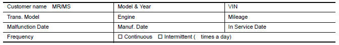
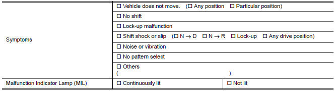
DIAGNOSTIC WORK SHEET
 Basic inspection
...
 Additional service when replacing TCM
Description
When replacing the TCM, perform the following work.
TCM PROGRAMMING
Since vehicle specifications are not yet written in a new TCM, it
is necessary to write them with CONSULT ...
Other materials:
Diagnosis system (BCM)
COMMON ITEM
COMMON ITEM : CONSULT Function (BCM - COMMON ITEM
APPLICATION ITEM
CONSULT performs the following functions via CAN communication with BCM.
SYSTEM APPLICATION
BCM can perform the following functions.
RETAINED PW
RETAINED PWR : CONSULT Function (BCM - RETAINED PWR)
DATA MONITO ...
Heater and Air Conditioner (automatic)
Front defroster button
Temperature control dial (driver's side)/
AUTO button
Display screen
Temperature control dial (passenger's
side)/DUAL button
Fresh air intake button
Air recirculation button
(air conditioner) button
(manual air flow control)
button
(fan speed cont ...
Key slot
Description
Detects whether Intelligent Key is inserted.
Immobilizer antenna amp checks Intelligent Key transponder.
Component Function Check
1. CHECK FUNCTION
With CONSULT
Check KEY SW -SLOT in Data Monitor mode with CONSULT.
Diagnosis Procedure
1. CHECK KEY SLOT POWER SUPPLY CIRCU ...
Nissan Maxima Owners Manual
- Illustrated table of contents
- Safety-Seats, seat belts and supplemental restraint system
- Instruments and controls
- Pre-driving checks and adjustments
- Monitor, climate, audio, phone and voice recognition systems
- Starting and driving
- In case of emergency
- Appearance and care
- Do-it-yourself
- Maintenance and schedules
- Technical and consumer information
Nissan Maxima Service and Repair Manual

0.0063