Nissan Maxima Service and Repair Manual: Interior room lamp control system
System Diagram
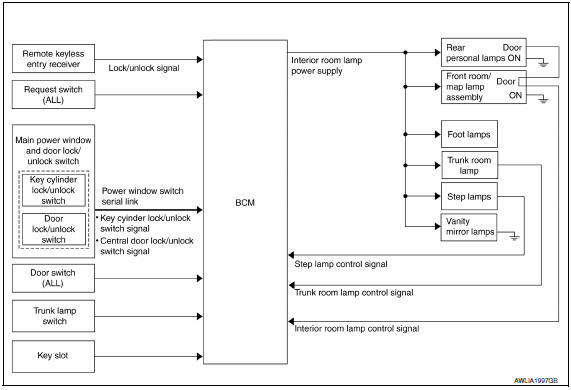
System Description
OUTLINE
- Interior room lamps* are controlled by interior room lamp timer
control function of BCM.
*:Front room/map lamp assembly, foot lamps and rear personal lamps (when front room/map lamp assembly switch is in DOOR position).
- Trunk room lamp is controlled by trunk room lamp control function of BCM.
- Step lamps are controlled by step lamp control function of BCM.
Component Parts Location
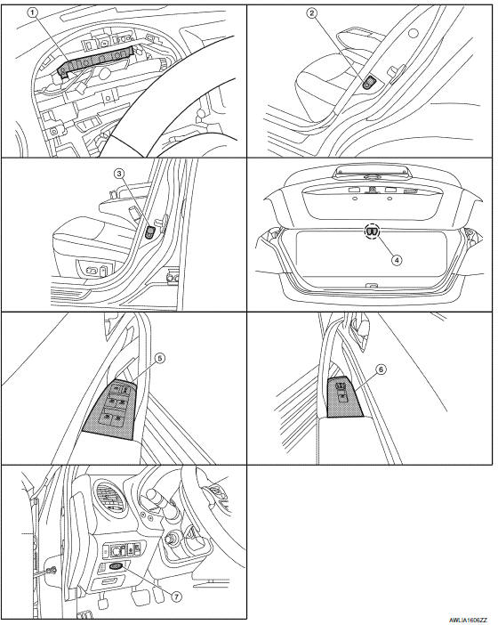
- BCM M16, M17, M18, M19, M20, M21 (view with combination meter removed)
- Rear door switch LH B18, RH B116
- Front door switch LH B8, RH B108
- Trunk lamp switch and trunk release solenoid T7
- Main power window and door lock/unlock switch D7, D8
- Power window and door lock/unlock switch RH D105
- Key slot M40
Component Description
SWITCH OPERATION
When a door is opened, the door switch closes to send a ground signal to the BCM. When the trunk is opened, the trunk lamp switch and trunk release solenoid closes sending a ground signal to the BCM.
ROOM LAMP TIMER OPERATION
When the front room/map lamp assembly switch is in DOOR position and when all conditions below are met, BCM begins timer control (maximum 30 seconds) for interior room lamp ON/OFF.
- When the front door LH is unlocked [with Intelligent Key, main power window and door lock/unlock switch, power window and door lock/unlock switch RH, or front door lock assembly (key cylinder switch)].
- When a door opens → closes and the Intelligent Key is not inserted
in the key slot.
Timer control is cancelled under the following conditions.
- When the front door LH is locked [with Intelligent Key, main power window and door lock/unlock switch, power window and door lock/unlock switch RH, or front door lock assembly (key cylinder switch)].
- A door is opened (door switch turns ON).
- Intelligent Key is inserted into the key slot.
Interior lamp operational settings can be changed with the function setting of CONSULT.
INTERIOR LAMP BATTERY SAVER CONTROL
If an interior lamp is left ON and does not turn OFF even when the doors are closed, the BCM turns off power to the interior lamps automatically to save the battery 15 minutes after the ignition switch is turned OFF.
The BCM controls the interior lamps listed below
- Front step lamp LH and RH
- Rear step lamp LH and RH
- Front room/map lamp assembly
- Foot lamp LH and RH
- Personal lamp rear LH and RH
- Vanity mirror lamp LH and RH
- Trunk room lamp
After the battery saver system turns the lamps OFF, the lamps will illuminate again when
- a signal is received from an Intelligent Key, main power window and door lock/unlock switch or power window and door lock/unlock switch RH, or when the front door LH lock assembly (key cylinder switch) is locked or unlocked
- a door is opened or closed
- the Intelligent Key is removed from or inserted into the key slot.
The interior lamp battery saver control time period can be changed with the function setting of CONSULT.

 Illumination control system
System Diagram
System Description
The illumination lamps operation is dependent upon the position of the
lighting switch (combination switch).
When the lighting switch is placed in
the 1ST or ...
Other materials:
ABS actuator and electric unit (control unit)
Exploded View
From master cylinder secondary side
Grommet
ABS actuator and electric unit (control
unit) bracket
From master cylinder primary side
To front LH brake caliper
To rear RH brake caliper
To rear LH brake caliper
To front RH brake caliper
ABS actuator and el ...
Rear power window switch
Removal and Installation
REMOVAL
Remove the rear door armrest finisher. Refer to INT-21,
"Removal and Installation".
Release the pawls on each side to separate the switch finisher
(1) from the rear power window switch (2) using a suitable tool
(A).
: Pawl
INSTALLA ...
Road test
Description
DESCRIPTION
The purpose of the test is to determine the
overall performance of
CVT and analyze causes of problems.
The road test consists of the following three
parts:
"Check Before Engine Is Started"TM-164.
"Check at ...
Nissan Maxima Owners Manual
- Illustrated table of contents
- Safety-Seats, seat belts and supplemental restraint system
- Instruments and controls
- Pre-driving checks and adjustments
- Monitor, climate, audio, phone and voice recognition systems
- Starting and driving
- In case of emergency
- Appearance and care
- Do-it-yourself
- Maintenance and schedules
- Technical and consumer information
Nissan Maxima Service and Repair Manual

0.0056