Nissan Maxima Service and Repair Manual: Illumination control system
System Diagram
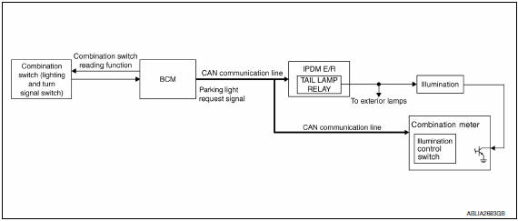
System Description
The illumination lamps operation is dependent upon the position of the lighting switch (combination switch).
When the lighting switch is placed in the 1ST or 2ND position (or if the auto light system is activated) the BCM (body control module) receives input requesting the illumination lamps to illuminate. This input is communicated to the IPDM E/R (intelligent power distribution module engine room) across the CAN communication lines. The CPU (central processing unit) of the IPDM E/R controls the tail lamp relay coil. When energized, this relay directs power to the illumination lamps, which then illuminate.
Component Parts Location
- IPDM E/R E17, E18
- BCM M16, M17, M18, M19 (view with combination meter removed)
- Combination switch (lighting and turn signal switch) M28
- Illumination control switch (built into combination meter)
Component Description
ILLUMINATION OPERATION BY LIGHTING SWITCH
With the lighting switch in the 1ST or 2ND position (or if the auto light system is activated), the BCM receives input requesting the illumination lamps to illuminate. This input is communicated to the IPDM E/R across the CAN communication lines. The CPU of the IPDM E/R controls the tail lamp relay coil which, when energized, directs power
BATTERY SAVER CONTROL
When the lighting switch (combination switch) is in the 1ST or 2ND position and the ignition switch is turned from ON or ACC to OFF, the battery saver control feature is activated. Under this condition, the illumination lamps remain illuminated for 15 minutes unless the lighting switch position is changed. If the lighting switch position is changed, then the illumination lamps are turned off after a 30 second delay. When the lighting switch is turned from OFF to 1ST or 2ND position (or if auto light system is activated) after illumination lamps have been turned off by the battery saver control, the illumination lamps illuminate again.
 Interior room lamp control system
System Diagram
System Description
OUTLINE
Interior room lamps* are controlled by interior room lamp timer
control function of BCM.
*:Front room/map lamp assembly, foot lamps and
rear pe ...
 Diagnosis system (BCM)
COMMON ITEM
COMMON ITEM : CONSULT Function (BCM - COMMON ITE
APPLICATION ITEM
CONSULT performs the following functions via CAN communication with BC
SYSTEM APPLICATION
BCM can perform the follo ...
Other materials:
Malfunction indicator lamp
Description
The Malfunction Indicator Lamp (MIL) is located on the combination
meter.
The MIL will illuminate when the ignition switch is turned ON without
the engine running. This is a bulb check.
When the engine is started, the MIL should turn off. If the MIL
remains illuminated, ...
Both side headlamps do not switch to high beam
Description
The headlamps (both sides) do not switch to high beam when the lighting
switch is in the HI or PASS setting.
Diagnosis Procedure
1.COMBINATION SWITCH (LIGHTING AND TURN SIGNAL SWITCH) INSPECTION
Check the combination switch (lighting and turn signal switch).
2.CHECK HEADLAMP (HI) ...
Memory storage function
Two positions for the driver's seat, steering column
(if so equipped), and outside mirrors can be stored
in the automatic drive positioner memory. Follow
these procedures to use the memory system.
1. Place the ignition in the ON or ACC position
(The vehicle should be stopped while setting ...
Nissan Maxima Owners Manual
- Illustrated table of contents
- Safety-Seats, seat belts and supplemental restraint system
- Instruments and controls
- Pre-driving checks and adjustments
- Monitor, climate, audio, phone and voice recognition systems
- Starting and driving
- In case of emergency
- Appearance and care
- Do-it-yourself
- Maintenance and schedules
- Technical and consumer information
Nissan Maxima Service and Repair Manual

0.0068