Nissan Maxima Service and Repair Manual: CAN communication circuit
Diagnosis Procedure
1.CONNECTOR INSPECTION
- Turn the ignition switch OFF.
- Disconnect the battery cable from the negative terminal.
- Disconnect all the unit connectors on CAN communication system.
- Check terminals and connectors for damage, bend and loose connection.
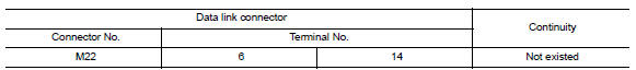
2.CHECK HARNESS CONTINUITY (SHORT CIRCUIT)
Check the continuity between the data link connector terminals.
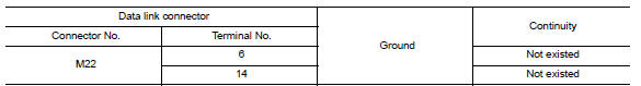
3.CHECK HARNESS CONTINUITY (SHORT CIRCUIT)
Check the continuity between the data link connector and the ground.
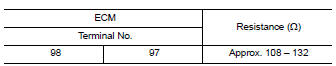
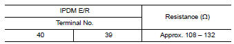
4.CHECK ECM AND IPDM E/R TERMINATION CIRCUIT
- Remove the ECM and the IPDM E/R.
- Check the resistance between the ECM terminals.
3. Check the resistance between the IPDM E/R terminals.
5.CHECK SYMPTOM
Connect all the connectors. Check if the symptoms described in the "Symptom (Results from interview with customer)" are reproduced.
Inspection result
Reproduced>>GO TO 6.
Non-reproduced>>Start the diagnosis again. Follow the trouble diagnosis procedure when past error is detected.
6.CHECK UNIT REPRODUCTION
Perform the reproduction test as per the following procedure for each unit.
- Turn the ignition switch OFF.
- Disconnect the battery cable from the negative terminal.
- Disconnect one of the unit connectors of CAN communication system.
NOTE: ECM and IPDM E/R have a termination circuit. Check other units first.
- Connect the battery cable to the negative terminal. Check if the
symptoms described in the "Symptom
(Results from interview with customer)" are reproduced.
NOTE: Although unit-related error symptoms occur, do not confuse them with other symptoms.
Inspection result
Reproduced>>Connect the connector. Check other units as per the above procedure.
Non-reproduced>>Replace the unit whose connector was disconnected.
 IPDM-E branch line circuit
Diagnosis Procedure
1.CHECK CONNECTOR
Turn the ignition switch OFF.
Disconnect the battery cable from the negative terminal.
Check the terminals and connectors of the IPDM E/R for damage,
...

Other materials:
P0327, P0328, P0332, P0333 KS
Description
The knock sensor is attached to the cylinder block. It senses engine knocking
using a piezoelectric element. A
knocking vibration from the cylinder block is sensed as vibrational pressure.
This pressure is converted into a
voltage signal and sent to the ECM.
DTC Logic
DTC DETE ...
Combination switch system symptoms
SYMPTOM DIAGNOSIS
COMBINATION SWITCH SYSTEM SYMPTOMS
Symptom Table
Perform the data monitor of CONSULT to check for any malfunctioning
item.
Check the malfunction combinations
Identify the malfunctioning part from the agreed combination and repair
or replace the part.
...
Unit removal and installation
TRANSMITTER
Exploded View
Transmitter (tire pressure sensor)
O-ring
Valve stem nut
Valve core
Valve cap
Valve stem assembly : Parts that are
replaced as a set when the tire is replaced.
Removal and Installation
REMOVAL
Remove road wheel and tire assembly using power t ...
Nissan Maxima Owners Manual
- Illustrated table of contents
- Safety-Seats, seat belts and supplemental restraint system
- Instruments and controls
- Pre-driving checks and adjustments
- Monitor, climate, audio, phone and voice recognition systems
- Starting and driving
- In case of emergency
- Appearance and care
- Do-it-yourself
- Maintenance and schedules
- Technical and consumer information
Nissan Maxima Service and Repair Manual

0.0059