Nissan Maxima Service and Repair Manual: Diagnosis and repair workflow
Work Flow
OVERALL SEQUENCE
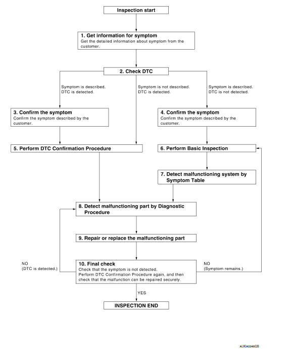
1.GET INFORMATION FOR SYMPTOM
Get the detailed information from the customer about the symptom (the condition and the environment when the incident/malfunction occurred).
2.CHECK DTC WITH BCM AND IPDM E/R
- Check "Self Diagnostic Result" with CONSULT.
- Perform the following procedure if DTC is displayed.
- Record DTC and freeze frame data (Print them out with CONSULT.)
- Erase DTC.
- Study the relationship between the cause detected by DTC and the symptom described by the customer.
3. Check related service bulletins for information.
Is any symptom described and any DTC detected?
Symptom is described, DTC is displayed.
Symptom is described, DTC is not displayed.
Symptom is not described, DTC is displayed.
3.CONFIRM THE SYMPTOM
Confirm the symptom described by the customer.
Connect CONSULT to the vehicle in "Data Monitor" mode and check real time diagnosis results.
Verify relationship between the symptom and the condition when the symptom is detected.
4.CONFIRM THE SYMPTOM
Confirm the symptom described by the customer.
Connect CONSULT to the vehicle in "Data Monitor " mode and check real time diagnosis results.
Verify relationship between the symptom and the condition when the symptom is detected.
5.PERFORM DTC CONFIRMATION PROCEDURE
Perform DTC Confirmation Procedure for the displayed DTC, and then check that DTC is detected again.
At this time, always keep CONSULT connected to the vehicle, and check diagnostic results in real time.
If two or more DTCs are detected, refer to SEC-115, "DTC Inspection Priority Chart" and determine trouble diagnosis order.
NOTE:
- Freeze frame data is useful if the DTC is not detected.
- Perform Component Function Check if DTC Confirmation
Procedure is not included in Service Manual. This
simplified check procedure is an effective alternative though DTC cannot be
detected during this check.
If the result of Component Function Check is NG, it is the same as the detection of DTC by DTC Confirmation Procedure.
6.PERFORM BASIC INSPECTION
Perform SEC-7, "Pre-Inspection for Multi-System Diagnostic".
Inspection End.
7.DETECT MALFUNCTIONING SYSTEM BY SYMPTOM TABLE
Detect malfunctioning system according to following symptom tables based on the confirmed symptom in step 4, and determine the trouble diagnosis order based on possible causes and symptoms.
- Intelligent Key system/engine start function: SEC-158, "Symptom Table".
- Vehicle security system: SEC-159, "Symptom Table".
- Nissan vehicle immobilizer system-NATS: SEC-160, "Symptom Table".
8.DETECT MALFUNCTIONING PART BY DIAGNOSTIC PROCEDURE
Inspect according to Diagnostic Procedure of the system.
NOTE:
The Diagnostic Procedure described based on open circuit inspection. A short circuit inspection is also required for the circuit check in the Diagnostic Procedure.
9.REPAIR OR REPLACE THE MALFUNCTIONING PART
- Repair or replace the malfunctioning part.
- Reconnect parts or connectors disconnected during Diagnostic Procedure again after repair or replacement.
- Check DTC. If DTC is displayed, erase it.
10.FINAL CHECK
When DTC was detected in step 2, perform DTC Confirmation Procedure or Component Function Check again, and then check that the malfunction has been fully repaired.
When symptom was described from the customer, refer to confirmed symptom in step 3 or 4, and check that the symptom is not detected.
 Basic inspection
...
 Pre-inspection for diagnostic
Pre-Inspection for Multi-System Diagnostic
The engine start function, door lock function, power distribution system and
NATS-IVIS/NVIS are closely
related to each other. Narrow down the system in ...
Other materials:
Front seat
Exploded View
DRIVER
Driver Seat - With Climate Controlled Seats
Seatback board
Seatback board clip
Seat cushion lower rear finisher
Seat harness
Seat cushion inner finisher inside (RH)
Recline mechanism inner cover
Seat cushion outer finisher (RH)
Seat belt buckle
Seat ...
Basic inspection
DIAGNOSIS AND REPAIR WORKFLOW
Work Flow
OVERALL SEQUENCE
DETAILED FLOW
1.INTERVIEW FOR MALFUNCTION
Find out what the customer's concerns are.
2.SYMPTOM CHECK
Verify the symptom from the customer's information.
3.BASIC INSPECTION
Check the operation of each part. Check that any concerns oc ...
Avoiding collision and rollover
WARNING
Failure to operate this vehicle in a safe
and prudent manner may result in loss of
control or an accident.
Be alert and drive defensively at all times. Obey
all traffic regulations. Avoid excessive speed,
high speed cornering, or sudden steering maneuvers,
because these driving practi ...
Nissan Maxima Owners Manual
- Illustrated table of contents
- Safety-Seats, seat belts and supplemental restraint system
- Instruments and controls
- Pre-driving checks and adjustments
- Monitor, climate, audio, phone and voice recognition systems
- Starting and driving
- In case of emergency
- Appearance and care
- Do-it-yourself
- Maintenance and schedules
- Technical and consumer information
Nissan Maxima Service and Repair Manual

0.0057