Nissan Maxima Service and Repair Manual: Headlamp
System Diagram
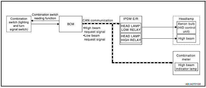
System Description
Control of the headlamp system is dependent upon the position of the combination switch (lighting and turn signal switch). When the lighting switch is placed in the 2nd position, the BCM (body control module) receives input requesting the headlamps and park lamps to illuminate. This input is communicated to the IPDM E/R (intelligent power distribution module engine room) across the CAN communication lines. The CPU (central processing unit) of the IPDM E/R controls the headlamp high and headlamp low relay coils. When energized, these relays direct power to the respective headlamps, which then illuminate.
Component Parts Location
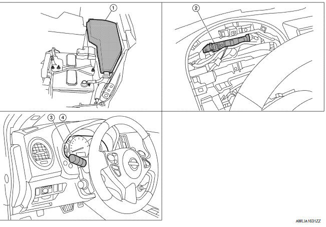
- IPDM E/R E17, E18, E200
- BCM M16, M17, M18, M19 (view with combination meter removed)
- Combination Switch (lighting and turn signal switch) M28
- Combination Meter M24
Component Description
XENON HEADLAMP
A Xenon type headlamp is adapted to the low beam headlamps. Xenon bulbs do not use a filament. Instead, they produce light when a high voltage current is passed between two tungsten electrodes through a mixture of Xenon (an inert gas) and certain other metal halides. In addition to added lighting power, electronic control of the power supply gives the headlamps stable quality and tone color.
Following are some of the many advantages of the Xenon-type headlamp.
- The light produced by the headlamps is a white color comparable to sunlight that is easy on the eyes.
- Light output is nearly double that of halogen headlamps, affording increased area of illumination.
- The light features a high relative spectral distribution at
wavelengths to which the human eye is most sensitive.
This means that even in the rain, more light is reflected back from the road surface toward the vehicle for added visibility.
- Power consumption is approximately 25 percent less than halogen headlamps, reducing battery load.
HIGH BEAM OPERATION/FLASH-TO-PASS OPERATION
With the lighting switch in the 2ND position and placed in HIGH position, the BCM receives input requesting the headlamp high beams to illuminate.The flash-to-pass feature can be used any time and also sends a signal to the BCM. This input is communicated to the IPDM E/R across the CAN communication lines. The CPU of the combination meter controls the ON/OFF status of the HIGH BEAM indicator. The CPU of the IPDM E/R controls the headlamp high relay coil which directs power to the high beam headlamps.
EXTERIOR LAMP BATTERY SAVER CONTROL
With the combination switch (lighting and turn signal switch) in the 2nd position and the ignition switch is turned from ON or ACC to OFF, the battery saver feature is activated.
Under this condition, the headlamps remain illuminated for 5 minutes unless the lighting switch position is changed. If the lighting switch position is changed, then the headlamps are turned off.
This setting can be changed by CONSULT. Refer to EXL-28, "BATTERY SAVER : CONSULT Function (BCM - BATTERY SAVER)".

 Daytime running light system
System Diagram
System Description
The headlamp system for Canada vehicles is equipped with a daytime light
relay that activates the high beam headlamps at approximately half
illumination whene ...
Other materials:
Symptom diagnosis
SQUEAK AND RATTLE TROUBLE DIAGNOSES
Work Flow
CUSTOMER INTERVIEW
Interview the customer if possible, to determine the conditions that exist
when the noise occurs. Use the Diagnostic Worksheet during the interview to
document the facts and conditions when the noise occurs and any customer' ...
Excessive ABS function operation frequency
Diagnosis Procedure
1.CHECK START
Check front and rear brake force distribution using a brake tester.
2.CHECK FRONT AND REAR AXLE
Make sure that there is no excessive play in the front and rear axles.
3.CHECK WHEEL SENSOR AND SENSOR ROTOR
Check the following:
Wheel sensor installation for ...
P1720 VSS
Description
ECM receives two vehicle speed signals via the CAN communication line. One is
sent from "ABS actuator and
electric unit (control unit)" via the combination meter, and the other is from
TCM (Transmission control module).
ECM uses these signals for engine control.
DTC Logic
DTC ...
Nissan Maxima Owners Manual
- Illustrated table of contents
- Safety-Seats, seat belts and supplemental restraint system
- Instruments and controls
- Pre-driving checks and adjustments
- Monitor, climate, audio, phone and voice recognition systems
- Starting and driving
- In case of emergency
- Appearance and care
- Do-it-yourself
- Maintenance and schedules
- Technical and consumer information
Nissan Maxima Service and Repair Manual

0.0054