Nissan Maxima Service and Repair Manual: Power control system
System Diagram
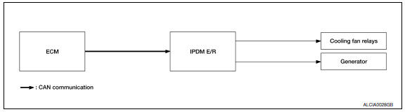
System Description
COOLING FAN CONTROL
IPDM E/R controls cooling fans according to the status of the cooling fan speed request signal received from ECM via CAN communication.
GENERATOR CONTROL
IPDM E/R outputs power generation command signal (PWM signal) to the generator according to the status of the power generation command value signal received from ECM via CAN communication. Refer to CHG-9, "System Description".
 Relay control system
System Diagram
System Description
IPDM E/R activates the internal control circuit to perform the relay ON-OFF
control according to the input signals
from various sensors and the request sign ...
 Signal buffer system
System Diagram
System Description
IPDM E/R reads the status of the oil pressure switch and transmits the
oil pressure switch signal to BCM via
CAN communication.
IPDM E/R receives the ...
Other materials:
Map lights
To turn the map lights on, push the switches. To
turn them off, push the switches again.
CAUTION
Do not use for extended periods of time
with the engine stopped. This could result
in a discharged battery.
Personal lights
To turn the rear personal lights on, push the
switch. To turn the ...
Front seat
Exploded View
DRIVER
Driver Seat - With Climate Controlled Seats
Seatback board
Seatback board clip
Seat cushion lower rear finisher
Seat harness
Seat cushion inner finisher inside (RH)
Recline mechanism inner cover
Seat cushion outer finisher (RH)
Seat belt buckle
Seat ...
Cup holders
Front cup holders
CAUTION
Avoid abrupt starting and braking when
the cup holder is being used to prevent
spilling the drink. If the liquid is hot, it
can scald you or your passenger. Spilled
liquid can also damage the seat climate
system.
Use only soft cups in the cup holder.
...
Nissan Maxima Owners Manual
- Illustrated table of contents
- Safety-Seats, seat belts and supplemental restraint system
- Instruments and controls
- Pre-driving checks and adjustments
- Monitor, climate, audio, phone and voice recognition systems
- Starting and driving
- In case of emergency
- Appearance and care
- Do-it-yourself
- Maintenance and schedules
- Technical and consumer information
Nissan Maxima Service and Repair Manual

0.0059