Nissan Maxima Service and Repair Manual: Signal buffer system
System Diagram
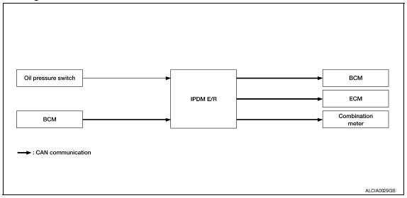
System Description
- IPDM E/R reads the status of the oil pressure switch and transmits the oil pressure switch signal to BCM via CAN communication.
- IPDM E/R receives the rear window defogger status signal from BCM via CAN communication and transmits it to ECM via CAN communication.
 Power control system
System Diagram
System Description
COOLING FAN CONTROL
IPDM E/R controls cooling fans according to the status of the cooling fan
speed request signal received from
ECM via CAN communication ...
 Power consumption control system
System Diagram
System Description
OUTLINE
IPDM E/R incorporates a power consumption control function that
reduces the power consumption according
to the vehicle status.
IPDM E/R chan ...
Other materials:
System description
COMPRESSOR CONTROL FUNCTION
Description
PRINCIPLE OF OPERATION
Compressor is not activated.
Functional circuit diagram
CAN (1): A/C switch signal
: Blower fan motor switch signal
CAN (2): A/C compressor request signal
Functional initial inspection chart
Fail-Safe
FAIL-SAFE FUNCTION ...
Floor mats
WARNING
To avoid potential pedal interference that
may result in a collision, injury or death:
NEVER place a floor mat on top of another
floor mat in the driver front
position.
Use only Genuine NISSAN floor mats
specifically designed for use in your vehicle
model. For additional in ...
DTC/circuit diagnosis
MAIN LINE BETWEEN DLC AND HVAC CIRCUIT
Diagnosis Procedure
1.CHECK HARNESS CONTINUITY (OPEN CIRCUIT)
Turn the ignition switch OFF.
Disconnect the battery cable from the negative terminal.
Disconnect the following harness connectors.
ECM
A/C auto amp.
Check the continuity betw ...
Nissan Maxima Owners Manual
- Illustrated table of contents
- Safety-Seats, seat belts and supplemental restraint system
- Instruments and controls
- Pre-driving checks and adjustments
- Monitor, climate, audio, phone and voice recognition systems
- Starting and driving
- In case of emergency
- Appearance and care
- Do-it-yourself
- Maintenance and schedules
- Technical and consumer information
Nissan Maxima Service and Repair Manual

0.0067