Nissan Maxima Service and Repair Manual: Rear window defogger relay
Description
Power is supplied to the rear window defogger with BCM control.
Component Function Check
1. CHECK REAR WINDOW DEFOGGER RELAY POWER SUPPLY CIRCUIT
Check that an operation noise of rear window defogger relay [located in fuse block (J/B)] can be heard when turning the rear window defogger switch ON.
Diagnosis Procedure
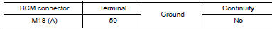
1. CHECK REAR WINDOW DEFOGGER RELAY GROUND CIRCUIT
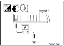
- Turn ignition switch ON.
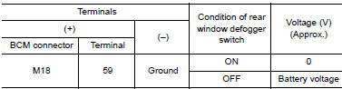
- Check voltage between BCM harness connector M18 terminal 59 and ground.
2. CHECK HARNESS CONTINUITY
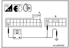
- Turn ignition switch OFF.
- Disconnect BCM and fuse block (J/B).
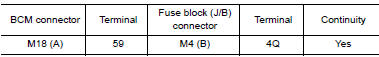
- Check continuity between BCM harness connector M18 (A) terminal 59 and fuse block (J/B) harness connector M4 (B) terminal 4Q.
- Check continuity between BCM harness connector M18 (A) terminal 59 and ground.
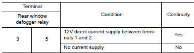
3. CHECK REAR WINDOW DEFOGGER RELAY
Check rear window defogger relay.
4. CHECK INTERMITTENT INCIDENT
Check intermittent incident
Component Inspection
1. CHECK REAR WINDOW DEFOGGER RELAY
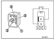
Check rear window defogger relay.
 Rear window defogger switch
Description
The rear window defogger is operated by turning the rear window defogger
switch ON.
Turns the indicator lamp in the rear window defogger switch ON
when operating the rear windo ...
 Rear window defogger power supply and ground circuit
Description
Heats the heating wire with the power supply from the rear window defogger
relay to prevent the rear window
from fogging up.
Component Function Check
1. CHECK REAR WINDOW DEFOGGER
...
Other materials:
Cleaning
If your windshield is not clear after using the
windshield-washer or if a wiper blade chatters
when running, wax or other material may be on
the blade or windshield.
Clean the outside of the windshield with a washer
solution or a mild detergent. Your windshield is
clean if beads do not form ...
P1722 vehicle speed
Description
The vehicle speed signal is transmitted from ABS actuator
and electric unit (control unit) to TCM via CAN communication
line.
DTC Logic
DTC DETECTION LOGIC
DTC CONFIRMATION PROCEDURE
CAUTION:
Always drive vehicle at a safe speed.
NOTE:
Immediately after performing any "DT ...
Audio unit
Removal and Installation
Audio unit brackets (LH/RH)
A/C auto amp.
Cluster lid C lower
Audio unit Clip
Pawl
REMOVAL
Disconnect the battery negative terminal. Refer to PG-67, "Removal
and Installation (Battery)".
Remove cluster lid D. Refer to IP-11, "Removal and In ...
Nissan Maxima Owners Manual
- Illustrated table of contents
- Safety-Seats, seat belts and supplemental restraint system
- Instruments and controls
- Pre-driving checks and adjustments
- Monitor, climate, audio, phone and voice recognition systems
- Starting and driving
- In case of emergency
- Appearance and care
- Do-it-yourself
- Maintenance and schedules
- Technical and consumer information
Nissan Maxima Service and Repair Manual

0.0049