Nissan Maxima Service and Repair Manual: Rear window defogger switch
Description
- The rear window defogger is operated by turning the rear window defogger switch ON.
- Turns the indicator lamp in the rear window defogger switch ON when operating the rear window defogger.
Component Function Check
1. CHECK REAR WINDOW DEFOGGER SWITCH FUNCTION
Check that the indicator lamp of rear window defogger illuminates with rear window defogger switch ON.
Diagnosis Procedure
1. CHECK A/C AUTO AMP. (REAR WINDOW DEFOGGER SWITCH)
Check A/C auto amp. operation
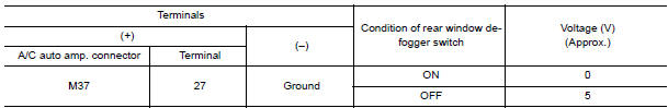
2.CHECK REAR WINDOW DEFOGGER SWITCH REQUIRE SIGNAL
- Turn ignition switch ON.
- Check voltage between A/C auto amp. harness connector M37 terminal 27 and ground
3. CHECK REAR WINDOW DEFOGGER SWITCH REQUIRE SIGNAL CIRCUIT FOR OPEN
- Turn ignition switch OFF.
- Disconnect A/C auto amp harness connector M37.
- Disconnect BCM harness connector M18.
- Check continuity between A/C auto amp harness connector M37 terminal 27 and BCM harness connector M18 terminal 38

4. CHECK REAR WINDOW DEFOGGER SWITCH REQUIRE SIGNAL CIRCUIT FOR SHORT
- Turn ignition switch OFF.
- Disconnect BCM harness connector M18.
- Disconnect A/C auto amp harness connector M37.
- Check continuity between BCM harness connector M18 terminal 38 and ground.


 Rear window defogger relay
Description
Power is supplied to the rear window defogger with BCM control.
Component Function Check
1. CHECK REAR WINDOW DEFOGGER RELAY POWER SUPPLY CIRCUIT
Check that an operation noise of rear ...
Other materials:
BCM (body control module)
Reference Value
NOTE:
The Signal Tech II Tool (J-50190) can be used to perform the
following functions. Refer to the Signal Tech II
User Guide for additional information.
Activate and display TPMS transmitter IDs
Display tire pressure reported by the TPMS transmitter
Read TPMS DTCs
R ...
Door lock function symptoms
DOOR LOCK AND UNLOCK SWITCH
DOOR LOCK AND UNLOCK SWITCH : Symptom Table
DOOR LOCK/UNLOCK FUNCTION MALFUNCTION
NOTE:
Before performing the diagnosis in the following table, check
"WORK FLOW". Refer to DLK-9, "Work Flow".
Check that vehicle is under the condition shown in "Condi ...
How to park with predicted course lines
WARNING
If the tires are replaced with different
sized tires, the predicted course lines
may be displayed incorrectly.
On a snow-covered or slippery road,
there may be a difference between the
predicted course line and the actual
course line.
If the battery is disconnected or becomes
discha ...
Nissan Maxima Owners Manual
- Illustrated table of contents
- Safety-Seats, seat belts and supplemental restraint system
- Instruments and controls
- Pre-driving checks and adjustments
- Monitor, climate, audio, phone and voice recognition systems
- Starting and driving
- In case of emergency
- Appearance and care
- Do-it-yourself
- Maintenance and schedules
- Technical and consumer information
Nissan Maxima Service and Repair Manual

0.0062