Nissan Maxima Service and Repair Manual: Door lock function symptoms
DOOR LOCK AND UNLOCK SWITCH
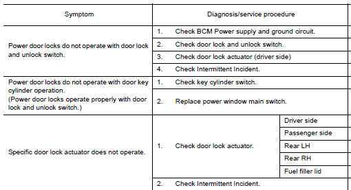
DOOR LOCK AND UNLOCK SWITCH : Symptom Table
DOOR LOCK/UNLOCK FUNCTION MALFUNCTION
NOTE:
- Before performing the diagnosis in the following table, check "WORK FLOW". Refer to DLK-9, "Work Flow".
- Check that vehicle is under the condition shown in "Conditions of vehicle" before starting diagnosis, and check each symptom.
- If the following symptoms are detected, check systems shown in the "Diagnosis/service procedure" column in this order.
Conditions of Vehicle (Operating Conditions)
- "LOCK/UNLOCK BY I-KEY" is ON when setting on CONSULT.
- Intelligent Key is out of key slot.
- All doors are closed.
DOOR REQUEST SWITCH
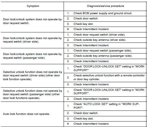
DOOR REQUEST SWITCH : Symptom Table
DOOR LOCK/UNLOCK FUNCTION MALFUNCTION
NOTE:
- Before performing the diagnosis in the following table, check "WORK FLOW". Refer to DLK-9, "Work Flow".
- Check that vehicle is under the condition shown in "Conditions of vehicle" before starting diagnosis, and check each symptom.
- If the following symptoms" are detected, check systems shown in the "Diagnosis/service procedure" column in this order.
Conditions of Vehicle (Operating Conditions)
- "LOCK/UNLOCK BY I-KEY" is ON when setting on CONSULT.
- Intelligent Key is out of key slot.
- All doors are closed.
INTELLIGENT KEY
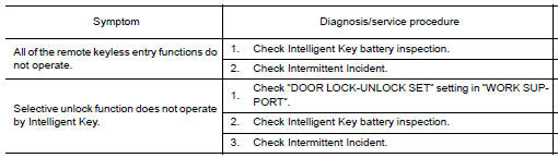
INTELLIGENT KEY : Symptom Table
REMOTE KEYLESS ENTRY FUNCTION MALFUNCTION
NOTE:
- Before performing the diagnosis in the following table, check "WORK FLOW". Refer to DLK-9, "Work Flow".
- Check that vehicle is under the condition shown in "Conditions of vehicle" before starting diagnosis, and check each symptom.
- If the following symptoms are detected, check systems shown in the "Diagnosis/service procedure" column in this order.
Conditions of Vehicle (Operating Conditions)
- Intelligent Key is out of key slot.
- Ignition switch is in OFF or ACC position.
- All doors are closed.
- Retained power operation does not operate
 Intelligent key system symptoms
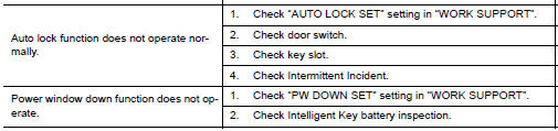
Symptom Table
ALL FUNCTIONS OF INTELLIGENT KEY SYSTEM DO NOT OPERATE
NOTE:
Before performing the diagnosis in the following table, check
"WORK FLOW". Refer to DLK-9, "Work Flow".
...
 Trunk open function symptoms
TRUNK LID OPENER SWITCH
TRUNK LID OPENER SWITCH : Symptom Table
TRUNK OPEN FUNCTION MALFUNCTION
NOTE:
Before performing the diagnosis in the following table, check
"WORK FLOW". Refer to DLK- ...
Other materials:
Power consumption control system
System Diagram
System Description
OUTLINE
BCM incorporates a power saving control function that reduces the
power consumption according to the
vehicle status.
BCM switches the status (control mode) by itself with the power
saving control function. It performs the sleep
reques ...
Precaution
PRECAUTIONS
Precaution for Supplemental Restraint System (SRS) "AIR BAG" and "SEAT
BELT
PRE-TENSIONER"
The Supplemental Restraint System such as "AIR BAG" and "SEAT BELT
PRE-TENSIONER", used along
with a front seat belt, helps to reduce the risk or severity of injury to ...
System description
INTELLIGENT KEY SYSTEM/ENGINE START FUNCTION
System Diagram
System Description
INPUT/OUTPUT SIGNAL CHART
SYSTEM DESCRIPTION
The engine start function of Intelligent Key system is a system
that makes it possible to start and stop the
engine without removing the key. It verifies the ...
Nissan Maxima Owners Manual
- Illustrated table of contents
- Safety-Seats, seat belts and supplemental restraint system
- Instruments and controls
- Pre-driving checks and adjustments
- Monitor, climate, audio, phone and voice recognition systems
- Starting and driving
- In case of emergency
- Appearance and care
- Do-it-yourself
- Maintenance and schedules
- Technical and consumer information
Nissan Maxima Service and Repair Manual

0.0095