
Nissan Maxima Service and Repair Manual: Rear window defogger power supply and ground circuit
Description
Heats the heating wire with the power supply from the rear window defogger relay to prevent the rear window from fogging up.
Component Function Check
1. CHECK REAR WINDOW DEFOGGER
Check that the heating wire of rear window defogger is heated when turning the rear window defogger switch ON.
Diagnosis Procedure
1. CHECK POWER SUPPLY CIRCUIT
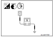
- Turn ignition switch ON.
- Check voltage between rear window defogger harness connector B53 terminal 1 and ground.
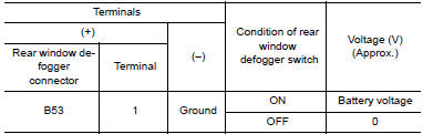
2. CHECK GROUND CIRCUIT
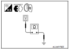
- Turn ignition switch OFF.
- Disconnect rear window defogger.
- Check continuity between rear window defogger harness connector B54 terminal 2 and ground.

3. CHECK HARNESS CONTINUITY 1
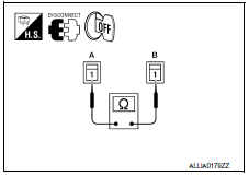
- Turn ignition switch OFF.
- Disconnect condenser and rear window defogger.
- Check continuity between condenser harness connector B52 (A) terminal 1 and rear window defogger harness connector B53 (B) terminal 1.

4. CHECK HARNESS CONTINUITY 2
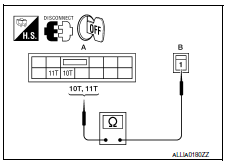
- Disconnect fuse block (J/B).
- Check continuity between fuse block (J/B) harness connector B4 (A) terminal 10T, 11T and condenser harness connector B52 (B) terminal 1.

5. CHECK FILAMENT
Check filament.
6. CHECK INTERMITTENT INCIDENT
Check intermittent incident
Component Inspection
1. CHECK FILAMENT
Check the filament for damage or open circuits.
 Rear window defogger relay
Description
Power is supplied to the rear window defogger with BCM control.
Component Function Check
1. CHECK REAR WINDOW DEFOGGER RELAY POWER SUPPLY CIRCUIT
Check that an operation noise of rear ...
 Driver side door mirror defogger
Description
Heats the heating wire with the power supply from the rear window defogger
relay to prevent the door mirror
from fogging up.
Component Function Check
1. CHECK DOOR MIRROR DEFOGGER L ...
Other materials:
Door lock actuator
DRIVER SIDE
DRIVER SIDE : Description
Locks/unlocks the door with the signal from BCM.
DRIVER SIDE : Component Function Check
1. CHECK FUNCTION
Use CONSULT to perform Active Test ("DOOR LOCK").
Touch "ALL LOCK" or "ALL UNLOCK" to check that it works normally.
DRIVER SIDE : Diagnosis ...
Main line between DLC and HVAC circuit
Diagnosis Procedure
1.CHECK HARNESS CONTINUITY (OPEN CIRCUIT)
Turn the ignition switch OFF.
Disconnect the battery cable from the negative terminal.
Disconnect the following harness connectors.
ECM
A/C auto amp.
Check the continuity between the data link connector and the A/C ...
ABS branch line circuit
Diagnosis Procedure
1.CHECK CONNECTOR
Turn the ignition switch OFF.
Disconnect the battery cable from the negative terminal.
Check the terminals and connectors of the ABS actuator and
electric unit (control unit) for damage, bend
and loose connection (unit side and connector side).
...
Nissan Maxima Owners Manual
- Illustrated table of contents
- Safety-Seats, seat belts and supplemental restraint system
- Instruments and controls
- Pre-driving checks and adjustments
- Monitor, climate, audio, phone and voice recognition systems
- Starting and driving
- In case of emergency
- Appearance and care
- Do-it-yourself
- Maintenance and schedules
- Technical and consumer information
Nissan Maxima Service and Repair Manual

0.0096