Nissan Maxima Service and Repair Manual: Key slot
Removal and Installation
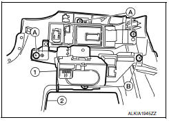
REMOVAL
-
Remove the instrument lower panel LH. Refer to IP-19, "Removal and Installation".
-
Remove the switch assembly screws (A), remove the key slot screws (B) and then remove key slot (1) from instrument lower panel LH (2).
INSTALLATION
Installation is in the reverse order of removal.

 Push button ignition switch
Removal and Installation
REMOVAL
Remove push-button ignition switch from cluster
lid A, using a suitable tool.
Disconnect harness connector from push-button
ignition ...
Other materials:
Installing the spare tire
The spare tire is designed for emergency
use. For additional information, refer to
"Wheels and tires" in the "Do-it-yourself"
section of this manual.
1. Clean any mud or dirt from the surface between
the wheel and hub.
2. Carefully put the spare tire on and tighten
the wheel nuts finger ...
BCM (body control module)
Reference Value
NOTE:The Signal Tech II Tool (J-50190) can
be used to perform the following functions. Refer to the Signal Tech IIUser
Guide for additional information.
Activate and display TPMS transmitter IDs
Display tire pressure reported by the TPMS transmitter
Read TPMS DTCs
Regi ...
Oil pump
Removal and Installation
REMOVAL
Remove the engine from the vehicle. Refer to EM-103, "Removal and
Installation".
Remove the upper oil pan. Refer to EM-37, "Removal and
Installation (Upper Oil Pan)".
Remove the timing chain. Refer to EM-64, "Removal and
Installati ...
Nissan Maxima Owners Manual
- Illustrated table of contents
- Safety-Seats, seat belts and supplemental restraint system
- Instruments and controls
- Pre-driving checks and adjustments
- Monitor, climate, audio, phone and voice recognition systems
- Starting and driving
- In case of emergency
- Appearance and care
- Do-it-yourself
- Maintenance and schedules
- Technical and consumer information
Nissan Maxima Service and Repair Manual

0.0065