Nissan Maxima Service and Repair Manual: Relay control system
System Diagram
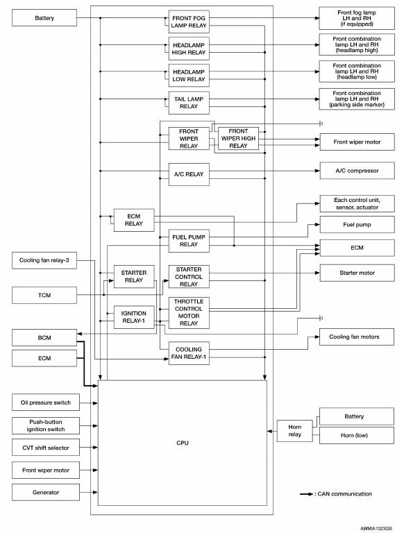
System Description
IPDM E/R activates the internal control circuit to perform the relay ON-OFF control according to the input signals from various sensors and the request signals received from control units via CAN communication.
CAUTION: IPDM E/R integrated relays cannot be removed
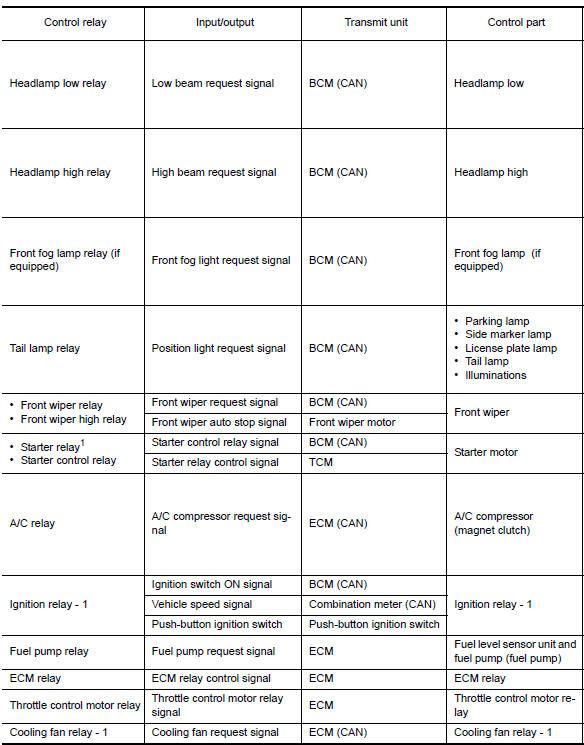
1: BCM controls the starter relay
Component Parts Location
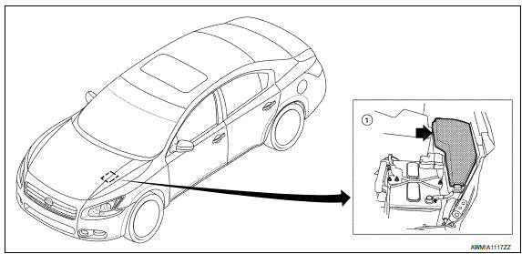
- IPDM E/R E16, E17, E18, E200, E201, F10

 Power control system
System Diagram
System Description
COOLING FAN CONTROL
IPDM E/R controls cooling fans according to the status of the cooling fan
speed request signal received from
ECM via CAN communication ...
Other materials:
L terminal circuit (open)
Description
The "L" terminal circuit controls the charge warning lamp. The charge warning
lamp turns ON when the ignition
switch is set to ON or START. When the generator is providing sufficient voltage
with the engine running,
the charge warning lamp turns OFF. If the charge warning lamp i ...
Inspection and adjustment
REAR VIEW MONITOR POSSIBLE ROUTE LINE CENTER POSITION ADJUSTMENT
REAR VIEW MONITOR POSSIBLE ROUTE LINE CENTER POSITION ADJUSTMENT :
Description
Adjust the center position of the possible route line of the rear view
monitor if it is shifted.
REAR VIEW MONITOR POSSIBLE ROUTE LINE CENTER POSITIO ...
Releasing the trunk lid
Press the button for longer than
1 second
to open the trunk lid. The trunk release button will
not operate when the ignition switch is in the ON
position or when the trunk cancel switch is in the
OFF position. For additional information, refer to
"Cancel switch" in this section. ...
Nissan Maxima Owners Manual
- Illustrated table of contents
- Safety-Seats, seat belts and supplemental restraint system
- Instruments and controls
- Pre-driving checks and adjustments
- Monitor, climate, audio, phone and voice recognition systems
- Starting and driving
- In case of emergency
- Appearance and care
- Do-it-yourself
- Maintenance and schedules
- Technical and consumer information
Nissan Maxima Service and Repair Manual

0.0058