Nissan Maxima Service and Repair Manual: P2135 TP sensor
Description
Electric throttle control actuator consists of throttle control motor, throttle position sensor, etc. The throttle position sensor responds to the throttle valve movement.
The throttle position sensor has two sensors. These sensors are a kind of potentiometers which transform the throttle valve position into output voltage, and emit the voltage signal to the ECM. In addition, these sensors detect the opening and closing speed of the throttle valve and feed the voltage signals to the ECM. The ECM judges the current opening angle of the throttle valve from these signals and the ECM controls the throttle control motor to make the throttle valve opening angle properly in response to driving condition.
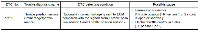
DTC Logic
DTC DETECTION LOGIC
NOTE: If DTC P2135 is displayed with DTC P0643, first perform the trouble diagnosis for DTC P0643. Refer to EC-394, "DTC Logic".
DTC CONFIRMATION PROCEDURE
1.PRECONDITIONING
If DTC Confirmation Procedure has been previously conducted, always perform the following before conducting the next test.
- Turn ignition switch OFF and wait at least 10 seconds.
- Turn ignition switch ON.
- Turn ignition switch OFF and wait at least 10 seconds.
TESTING CONDITION: Before performing the following procedure, confirm that battery voltage is more than 8 V at idle.
2.PERFORM DTC CONFIRMATION PROCEDURE
- Start engine and let it idle for 1 second.
- Check DTC.
Diagnosis Procedure
1.CHECK GROUND CONNECTION
- Turn ignition switch OFF.
- Check ground connection E9.
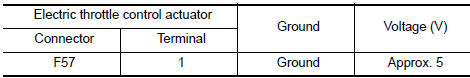
2.CHECK THROTTLE POSITION SENSOR POWER SUPPLY CIRCUIT-I
- Disconnect electric throttle control actuator harness connector.
- Turn ignition switch ON.
- Check the voltage between electric throttle control actuator harness connector and ground.
3.CHECK THROTTLE POSITION SENSOR GROUND CIRCUIT FOR OPEN AND SHORT
- Turn ignition switch OFF.
- Disconnect ECM harness connector.
- Check the continuity between electric throttle control actuator harness connector and ECM harness connector.
- Also check harness for short to ground and short to power.
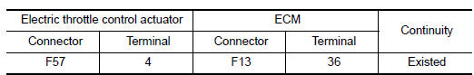
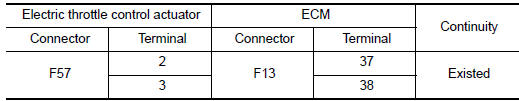
4.CHECK THROTTLE POSITION SENSOR INPUT SIGNAL CIRCUIT FOR OPEN AND SHORT
- Check the continuity between electric throttle control actuator harness connector and ECM harness connector.
- Also check harness for short to ground and short to power.
5.CHECK THROTTLE POSITION SENSOR
6.REPLACE ELECTRIC THROTTLE CONTROL ACTUATOR
- Replace electric throttle control actuator
7.CHECK INTERMITTENT INCIDENT
Component Inspection
1.CHECK THROTTLE POSITION SENSOR
- Turn ignition switch OFF.
- Reconnect all harness connectors disconnected.
- Perform EC-476, "Special Repair Requirement".
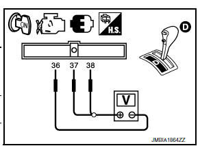
- Turn ignition switch ON.
- Set selector lever to D position.
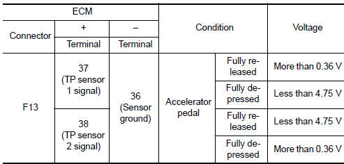
- Check the voltage between ECM harness connector terminals under the following conditions.
2.REPLACE ELECTRIC THROTTLE CONTROL ACTUATOR
- Replace electric throttle control actuator
Special Repair Requirement
1.PERFORM THROTTLE VALVE CLOSED POSITION LEARNING
2.PERFORM IDLE AIR VOLUME LEARNING
 P2127, P2128 APP sensor
Description
The accelerator pedal position sensor is installed on the upper end
of the accelerator pedal assembly. The sensor detects the accelerator
position and sends a signal to the ECM.
...
 P2138 APP sensor
Description
The accelerator pedal position sensor is installed on the upper end
of the accelerator pedal assembly. The sensor detects the accelerator
position and sends a signal to the ECM.
Ac ...
Other materials:
B257B, B257C ambient sensor
Description
COMPONENT DESCRIPTION
Ambient Sensor
The ambient sensor (1) is installed to the front bumper
reinforcement.
It detects ambient temperature and converts it into a resistance
value which is then input into the A/C auto amp.
Ambient Sensor Circuit
AMBIENT TEMPERATUR ...
Windows
Power windows
WARNING
Make sure that all passengers have
their hands, etc. inside the vehicle while
it is in motion and before closing the
windows. Use the window lock switch to
prevent unexpected use of the power
windows.
To help avoid risk of injury or death
through unintended o ...
Audible reminders
Brake pad wear warning
The disc brake pads have audible wear warnings.
When a disc brake pad requires replacement, it
makes a high pitched scraping sound when the
vehicle is in motion, whether or not the brake
pedal is depressed. Have the brakes checked as
soon as possible if the warning sou ...
Nissan Maxima Owners Manual
- Illustrated table of contents
- Safety-Seats, seat belts and supplemental restraint system
- Instruments and controls
- Pre-driving checks and adjustments
- Monitor, climate, audio, phone and voice recognition systems
- Starting and driving
- In case of emergency
- Appearance and care
- Do-it-yourself
- Maintenance and schedules
- Technical and consumer information
Nissan Maxima Service and Repair Manual

0.0076