Nissan Maxima Service and Repair Manual: BCM (body control module)
Reference Value
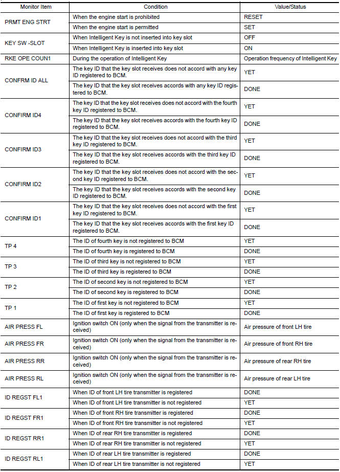
NOTE: The Signal Tech II Tool (J-50190) can be used to perform the following functions. Refer to the Signal Tech II User Guide for additional information.
- Activate and display TPMS transmitter IDs
- Display tire pressure reported by the TPMS transmitter
- Read TPMS DTCs
- Register TPMS transmitter IDs
- Check Intelligent Key relative signal strength
- Confirm vehicle Intelligent Key antenna signal strength
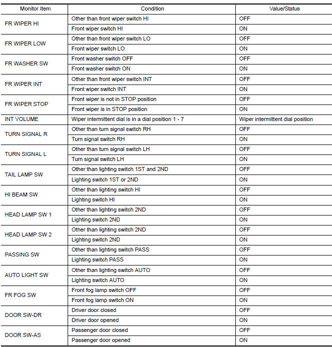
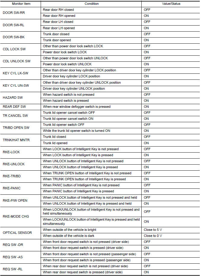
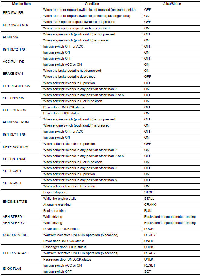
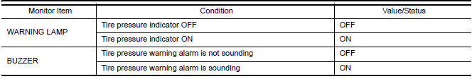
VALUES ON THE DIAGNOSIS TOOL
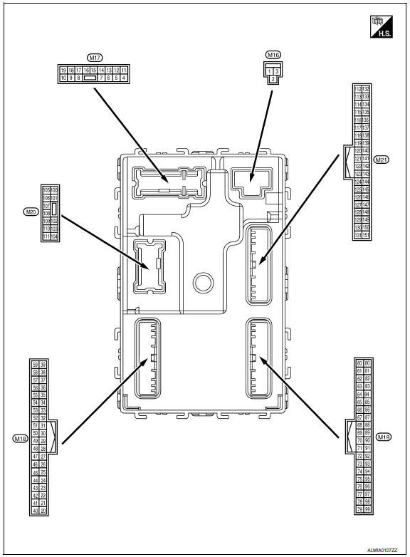
Terminal Layout
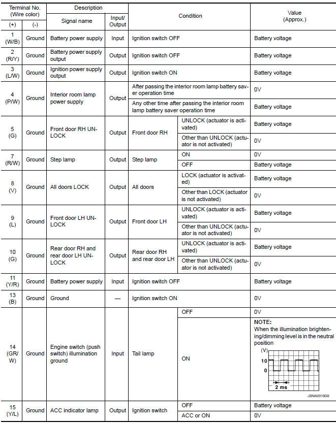
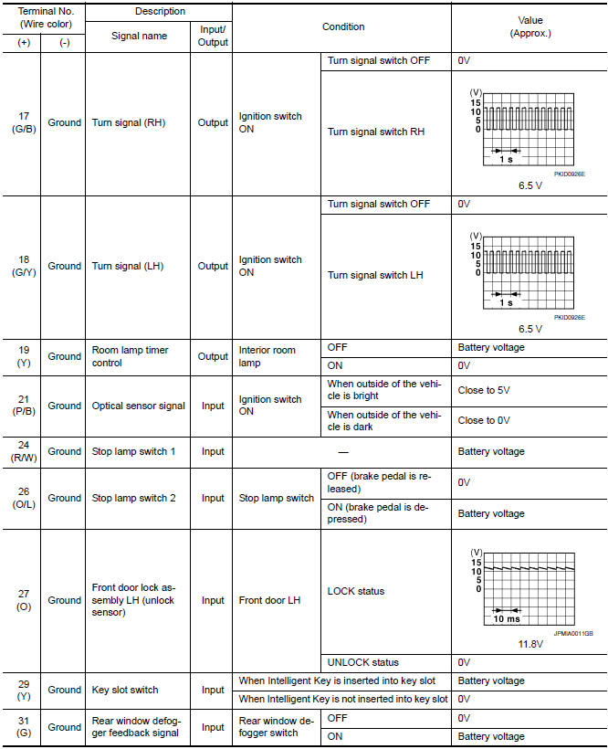
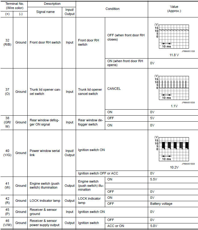
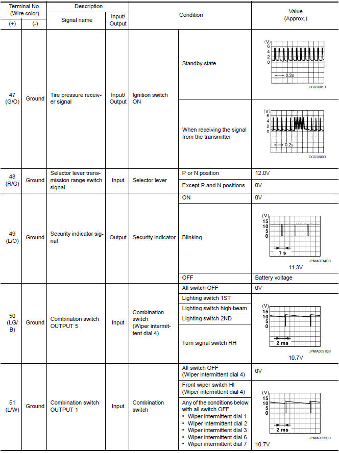
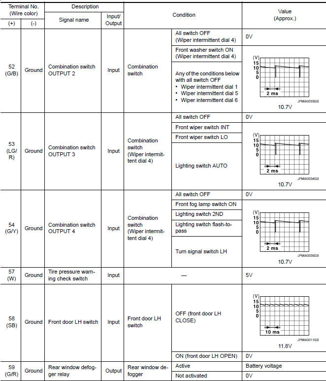
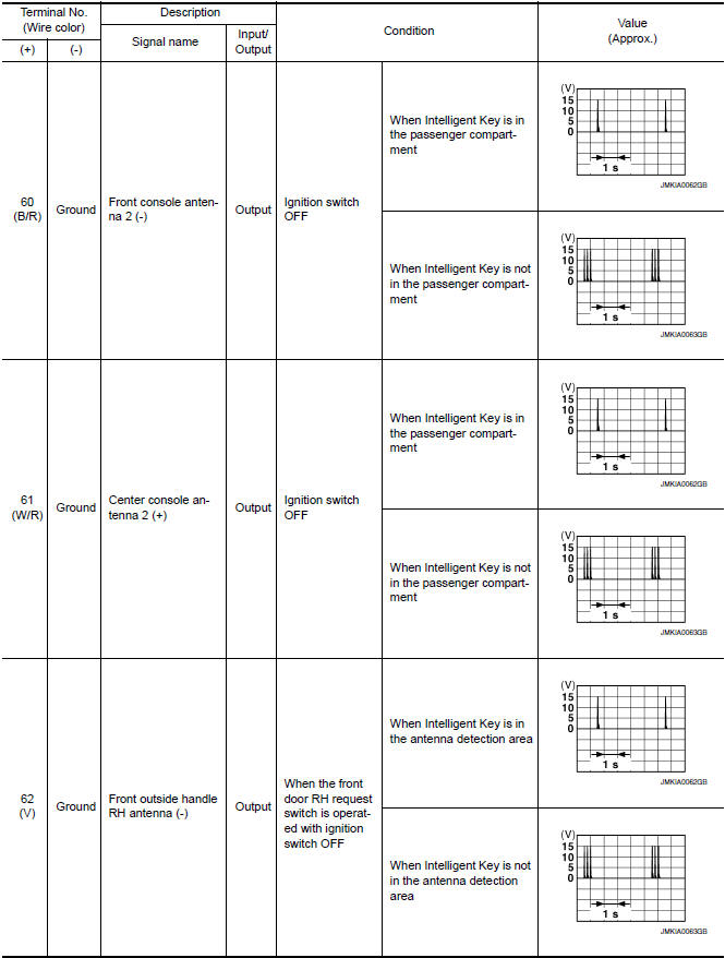
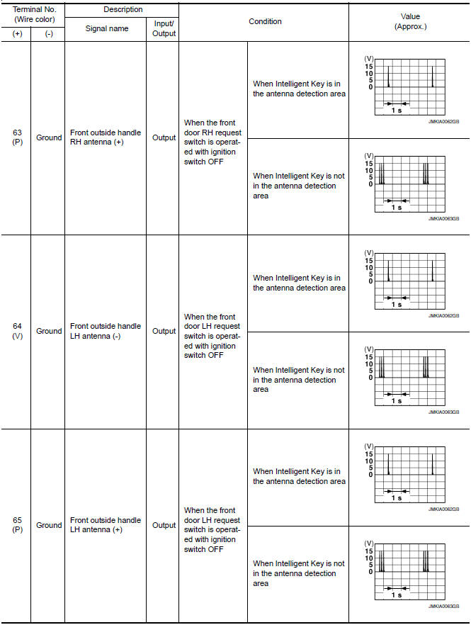
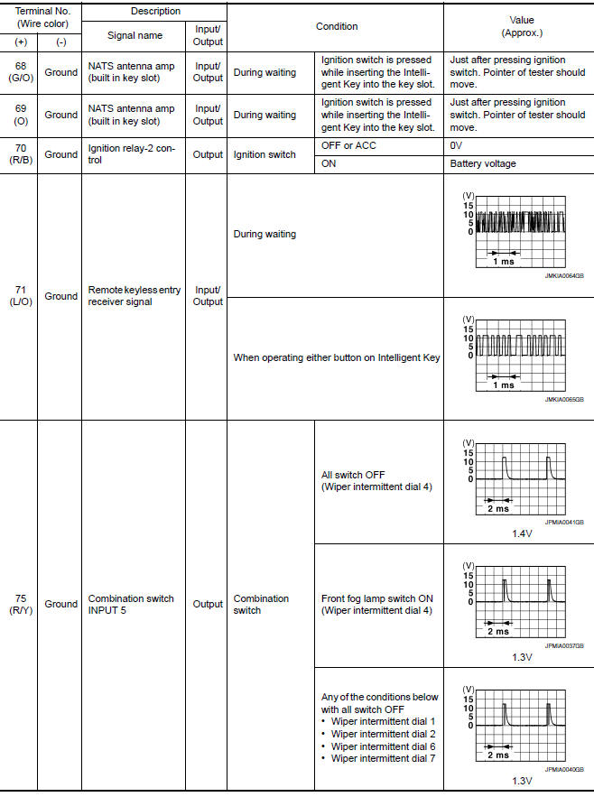
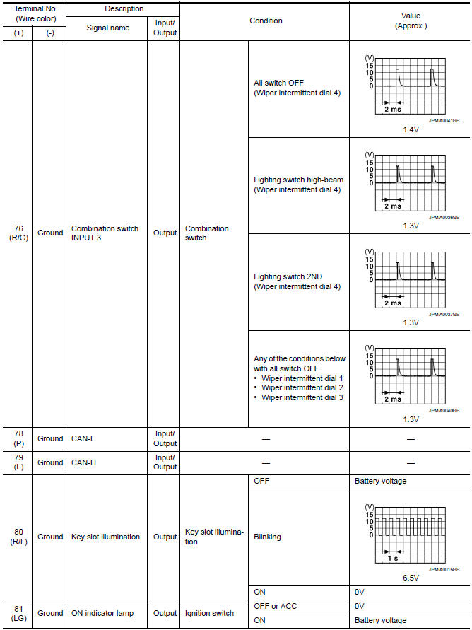
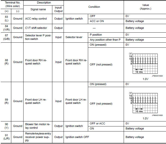
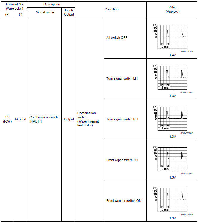
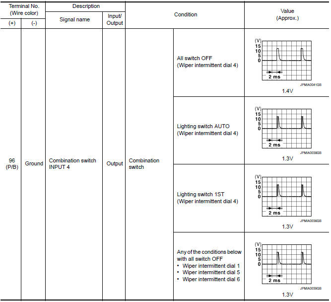
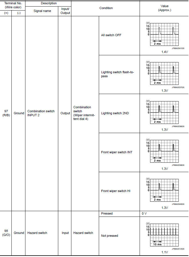
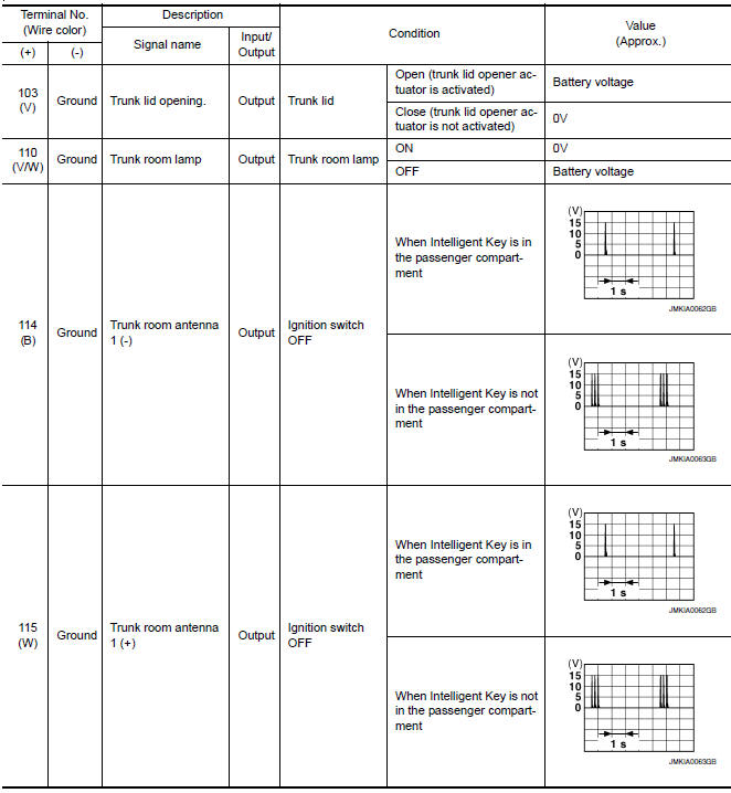
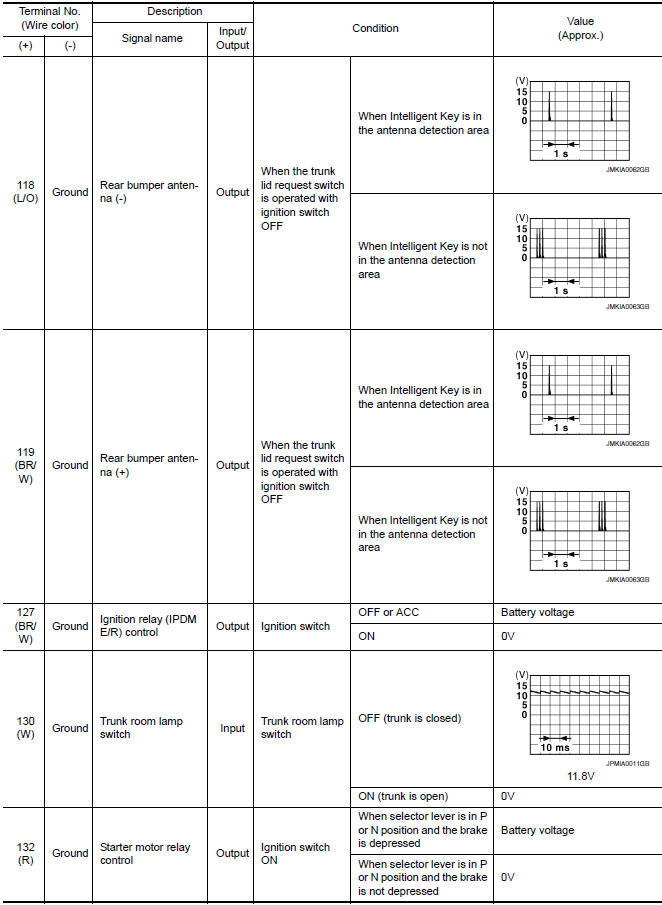
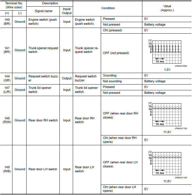
Physical Values
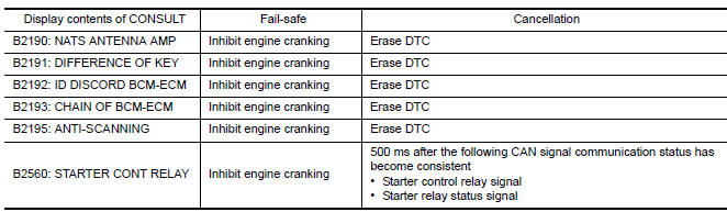
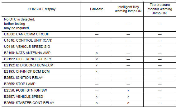
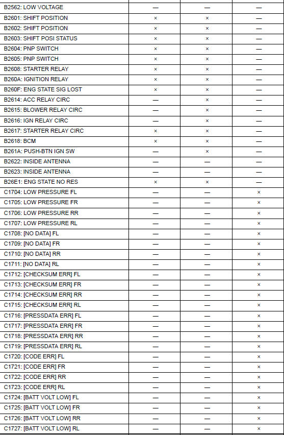
Fail Safe

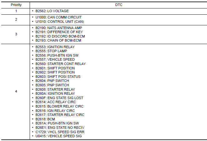
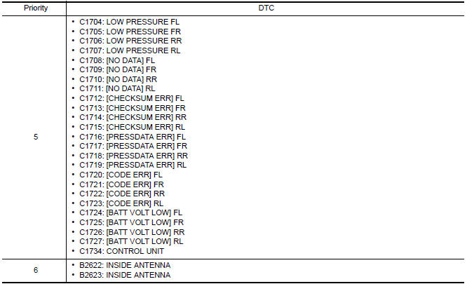
DTC Inspection Priority Chart
If some DTCs are displayed at the same time, perform inspections one by one based on the following priority chart.
DTC Index
NOTE: Details of time display
- CRNT: Displays when there is a malfunction now or after returning to the normal condition until turning ignition switch OFF → ON again.
- 1 - 39: Displayed if any previous malfunction is present when current condition is normal. It increases 1 → 2 → 3...38 → 39 after returning to the normal condition whenever ignition switch OFF → ON. The counter remains at 39 even if the number of cycles exceeds it. It is counted from 1 again when turning ignition switch OFF → ON after returning to the normal condition if the malfunction is detected again.

 Power window and door lock/unlock switch RH
Reference Value
TERMINAL LAYOUT
PHYSICAL VALUES
POWER WINDOW AND DOOR LOCK/UNLOCK SWITCH RH
Fail Safe
FAIL-SAFE CONTROL
Switches to fail-safe control when malfunction is detected in ...
 Wiring diagram
POWER WINDOW SYSTEM
Wiring Diagram
...
Other materials:
Audio system
Symptom Table
AUDIO SYSTEM
RELATED TO HANDS-FREE PHONE
Before performing diagnosis, confirm that the cellular phone being
used by the customer is compatible with
the vehicle.
It is possible that a malfunction is occurring due to a version
change of the phone even tho ...
B2634, B2635 air mix door motor (passenger side)
Description
COMPONENT DESCRIPTION
Air Mix Door Motor (Passenger Side)
The air mix door motor (passenger side) (1) is attached to the
heater & cooling unit assembly.
It rotates so that the air mix door is opened or closed to a
position
set by the A/C auto amp.
Motor rotation is t ...
U1255 satellite radio tuner
Descriptio
Part name
Description
SATELLITE RADIO TUNER
Inputs the satellite radio signal from satellite radio antenna
and outputs the sound signal to the AV control unit.
It is controlled with the AV control unit and serial
communicatio ...
Nissan Maxima Owners Manual
- Illustrated table of contents
- Safety-Seats, seat belts and supplemental restraint system
- Instruments and controls
- Pre-driving checks and adjustments
- Monitor, climate, audio, phone and voice recognition systems
- Starting and driving
- In case of emergency
- Appearance and care
- Do-it-yourself
- Maintenance and schedules
- Technical and consumer information
Nissan Maxima Service and Repair Manual

0.0057