Nissan Maxima Service and Repair Manual: Clip list
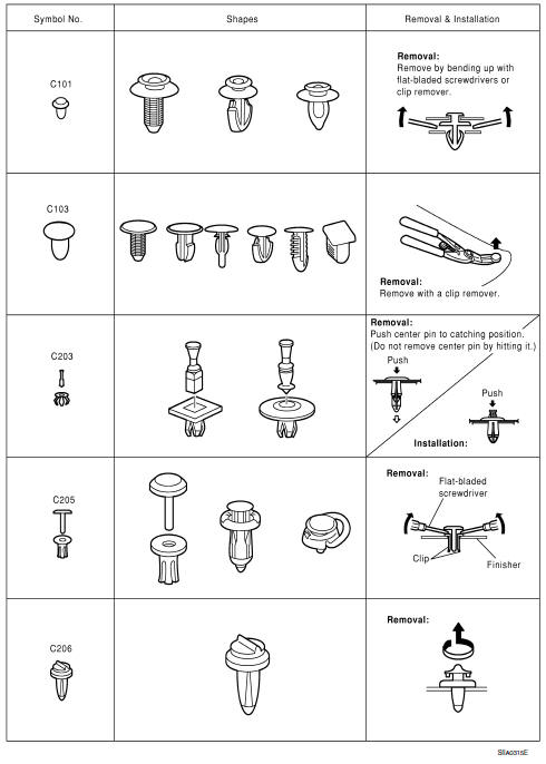
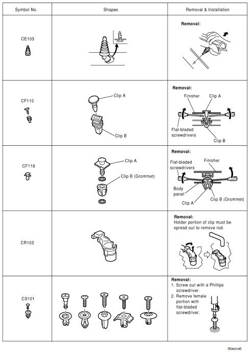
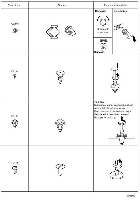
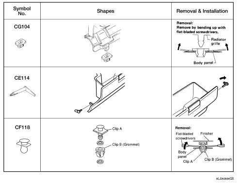
Descriptions for Clips
Replace any clips which are damaged during removal or installation.
 Preparation
Special Service Tools
...

Other materials:
Vertical synchronizing (VP) signal circuit
Description
In composite image (AUX image, camera image), transmit the vertical
synchronizing (VP) signal and horizontal synchronizing (HP) signal from
display unit to AV control unit so as to synchronize the RGB images displayed
with AV control unit, such as the image quality adjusting menu, ...
Unit removal and installation
TRANSAXLE ASSEMBLY
Exploded View
Air breather hose
CVT fluid level gauge
CVT fluid charging pipe
O-ring
Copper sealing washer
Fluid cooler tube
Transaxle assembly
A. Refer to INSTALLATION.
...
Maintenance precautions
When performing any inspection or maintenance
work on your vehicle, always take care to prevent
serious accidental injury to yourself or damage to
the vehicle. The following are general precautions
which should be closely observed.
WARNING
Park the vehicle on a level surface, apply
the pa ...
Nissan Maxima Owners Manual
- Illustrated table of contents
- Safety-Seats, seat belts and supplemental restraint system
- Instruments and controls
- Pre-driving checks and adjustments
- Monitor, climate, audio, phone and voice recognition systems
- Starting and driving
- In case of emergency
- Appearance and care
- Do-it-yourself
- Maintenance and schedules
- Technical and consumer information
Nissan Maxima Service and Repair Manual

0.0075