Nissan Maxima Service and Repair Manual: Power window and door lock/unlock switch RH
Reference Value
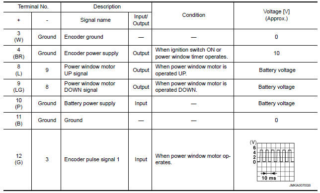
TERMINAL LAYOUT
PHYSICAL VALUES
POWER WINDOW AND DOOR LOCK/UNLOCK SWITCH RH
Fail Safe
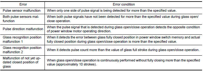
FAIL-SAFE CONTROL
Switches to fail-safe control when malfunction is detected in encoder signal that detects up/down speed and direction of door glass. Switches to fail-safe control when error beyond regulation value is detected between the fully closed position and the actual position of the glass.
It changes to condition before initialization and the following functions do not operate when switched to failsafe control:
- Auto-up operation
- Anti-pinch function
- Retained power function
Perform initial operation to recover when switched to fail-safe mode. However, it switches back to fail-safe control when malfunction is found in power window switch or in motor.
 Power window main switch
Reference Value
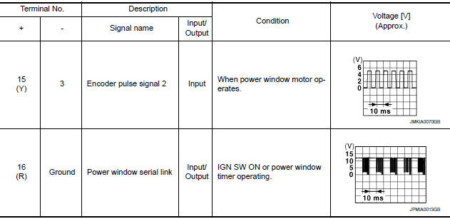
TERMINAL LAYOUT
PHYSICAL VALUES
MAIN POWER WINDOW AND DOOR LOCK/UNLOCK SWITCH
Fail Safe
FAIL-SAFE CONTROL
Switches to fail-safe control when malfunction is detected i ...
 BCM (body control module)
Reference Value
NOTE:
The Signal Tech II Tool (J-50190) can be used to perform the following
functions. Refer to the Signal Tech II
User Guide for additional information.
Activate and displ ...
Other materials:
U1243 display unit
Description
Part name
Description
DISPLAY UNIT
Display image is controlled by the serial communication from AV
control unit.
Inputs the RGB image signal (RGB, RGB area and RGB
synchronizing) from AV control unit and the auxiliary image ...
C1734 control unit
Description
An internal malfunction has been detected in the TPMS function of the BCM.
DTC Logic
NOTE: The Signal Tech II Tool (J-50190) can
be used to perform the following functions. Refer to the Signal Tech II User
Guide for additional information.
Activate and display TPMS trans ...
P0131, P0151 A/F sensor 1
Description
The air fuel ratio (A/F) sensor 1 is a planar one-cell limit current sensor.
The sensor element of the A/F sensor 1 is composed an electrode
layer, which transports ions. It has a heater in the element.
The sensor is capable of precise measurement = 1, but also in the
lean ...
Nissan Maxima Owners Manual
- Illustrated table of contents
- Safety-Seats, seat belts and supplemental restraint system
- Instruments and controls
- Pre-driving checks and adjustments
- Monitor, climate, audio, phone and voice recognition systems
- Starting and driving
- In case of emergency
- Appearance and care
- Do-it-yourself
- Maintenance and schedules
- Technical and consumer information
Nissan Maxima Service and Repair Manual

0.0053