Nissan Maxima Service and Repair Manual: BCM (body control module)
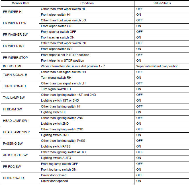
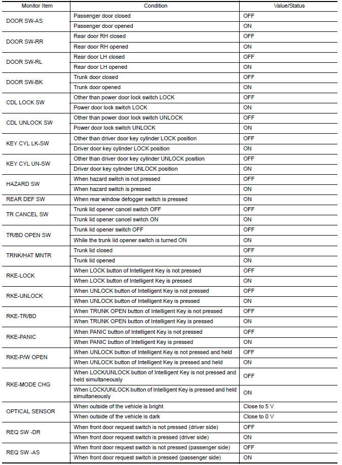
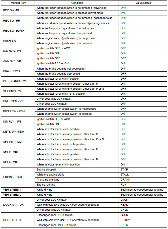
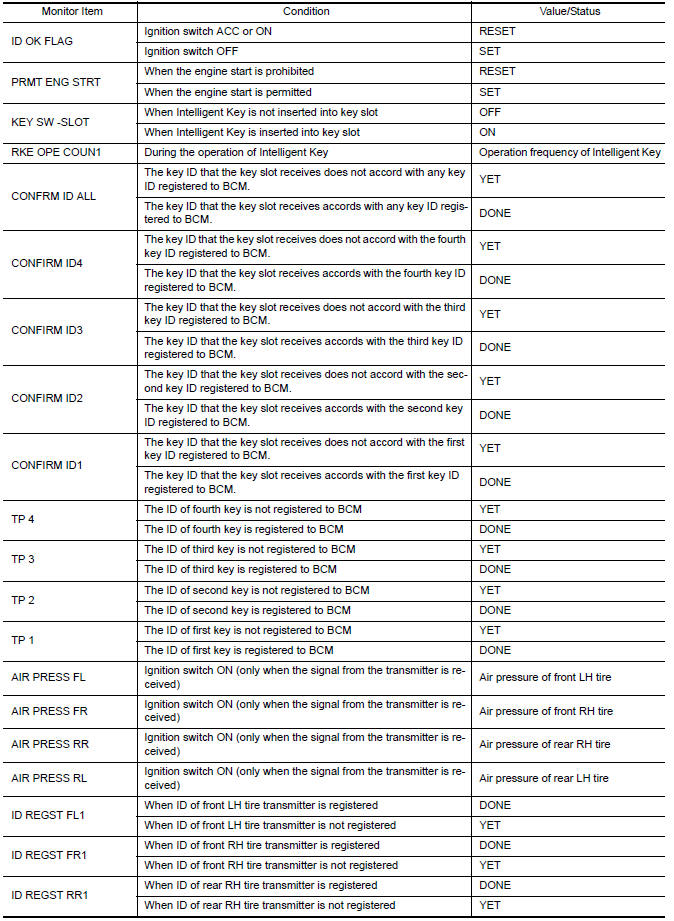
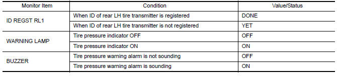
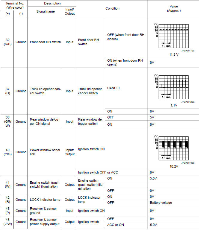
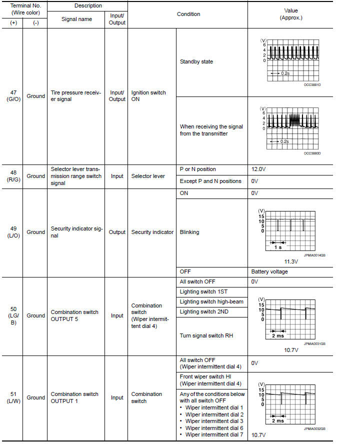
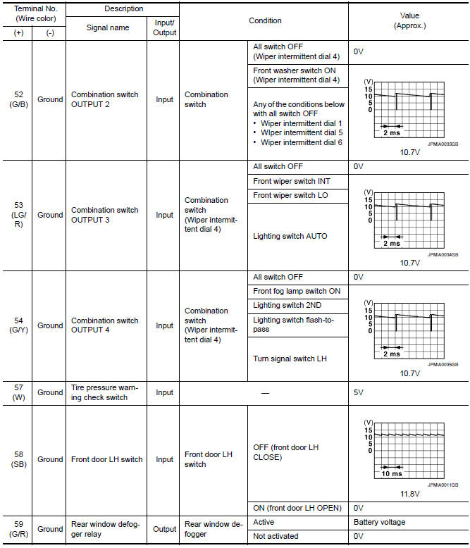
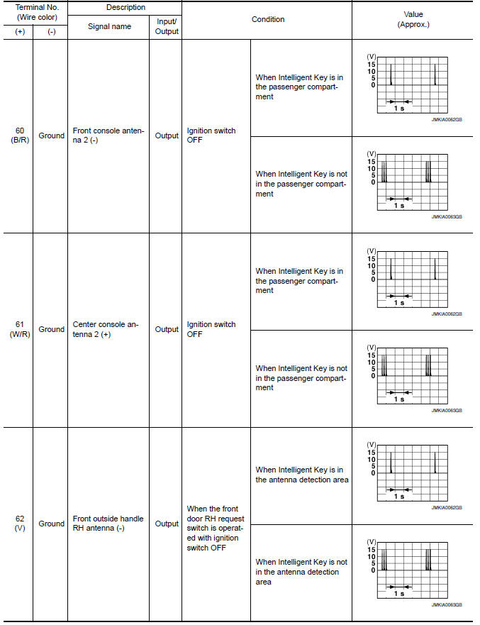
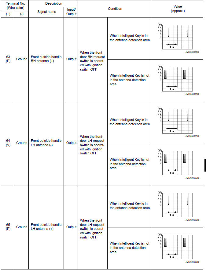
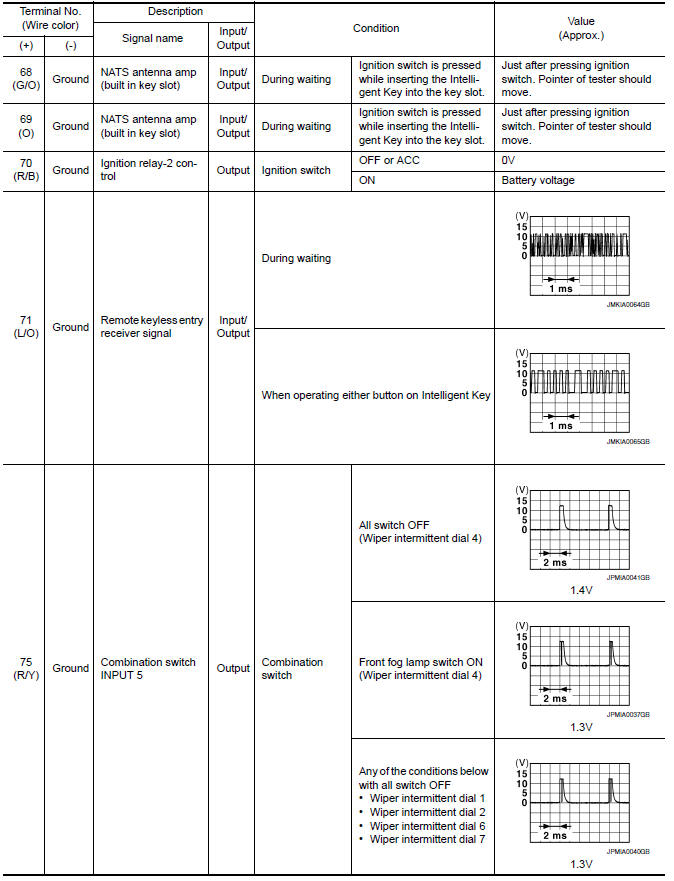
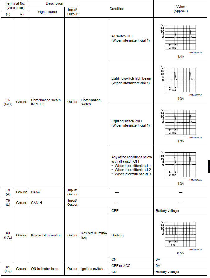
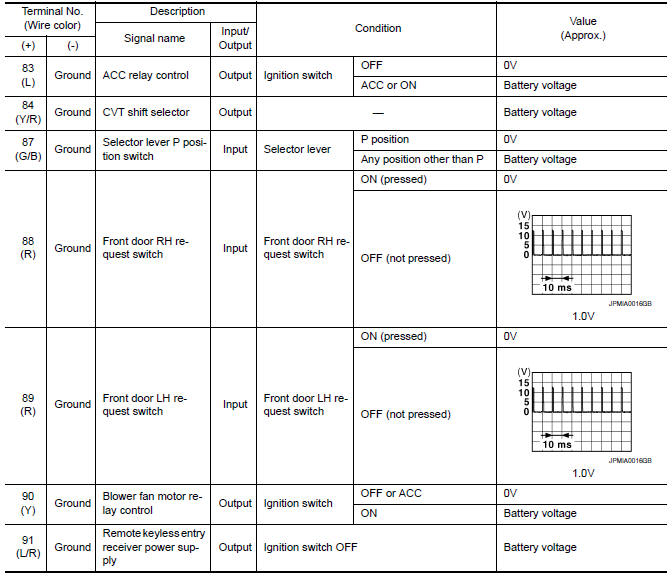
Reference Value
NOTE:
The Signal Tech II Tool (J-50190) can be used to perform the following functions. Refer to the Signal Tech II User Guide for additional information.
-
Activate and display TPMS transmitter IDs
-
Display tire pressure reported by the TPMS transmitter
-
Read TPMS DTCs
-
Register TPMS transmitter IDs
-
Check Intelligent Key relative signal strength
-
Confirm vehicle Intelligent Key antenna signal strength
VALUES ON THE DIAGNOSIS TOOL
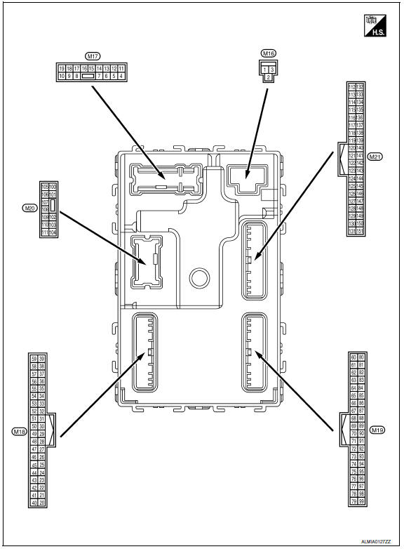
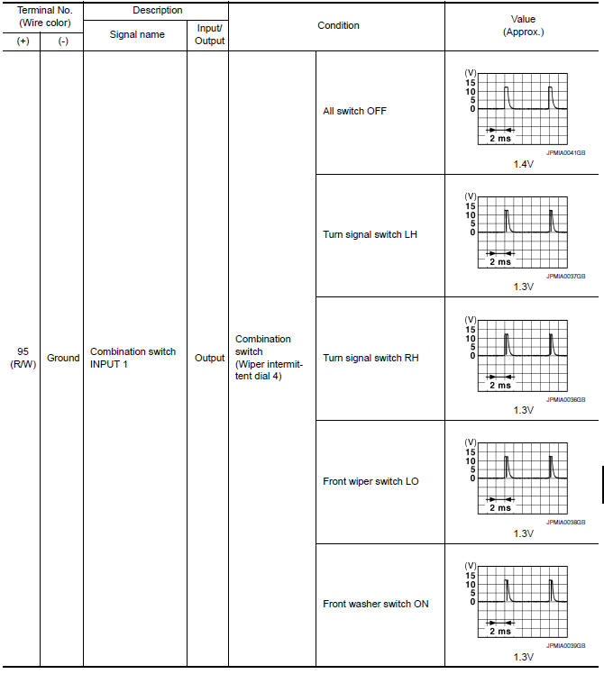
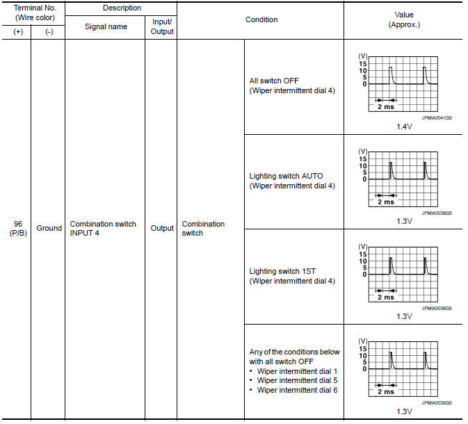
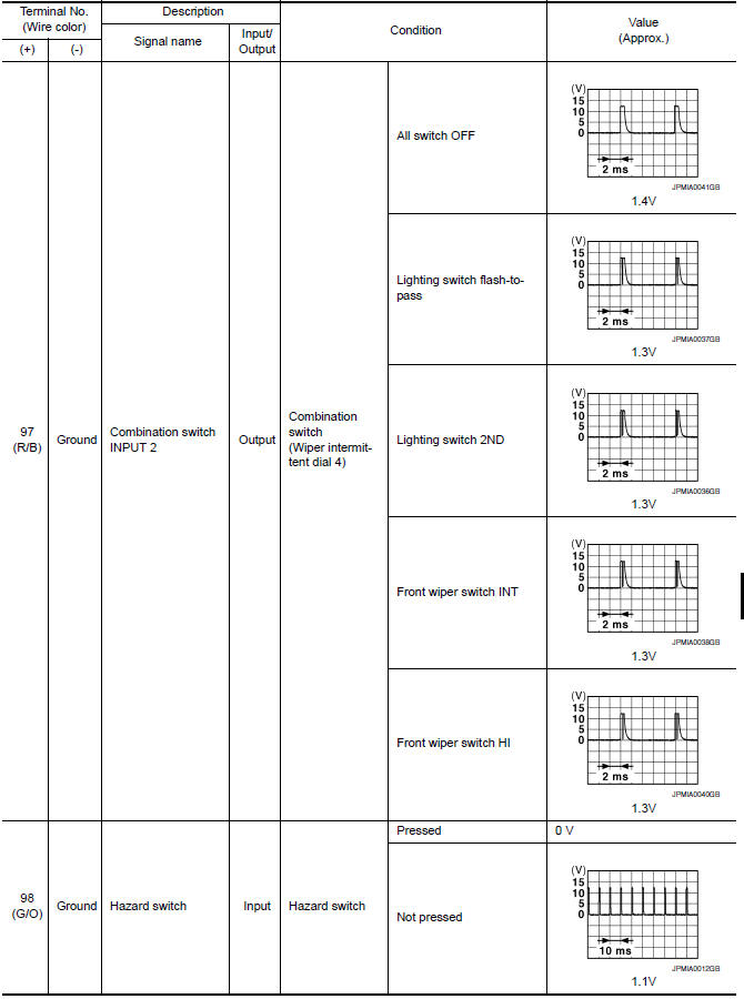
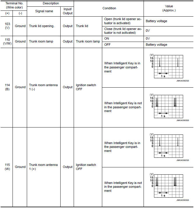
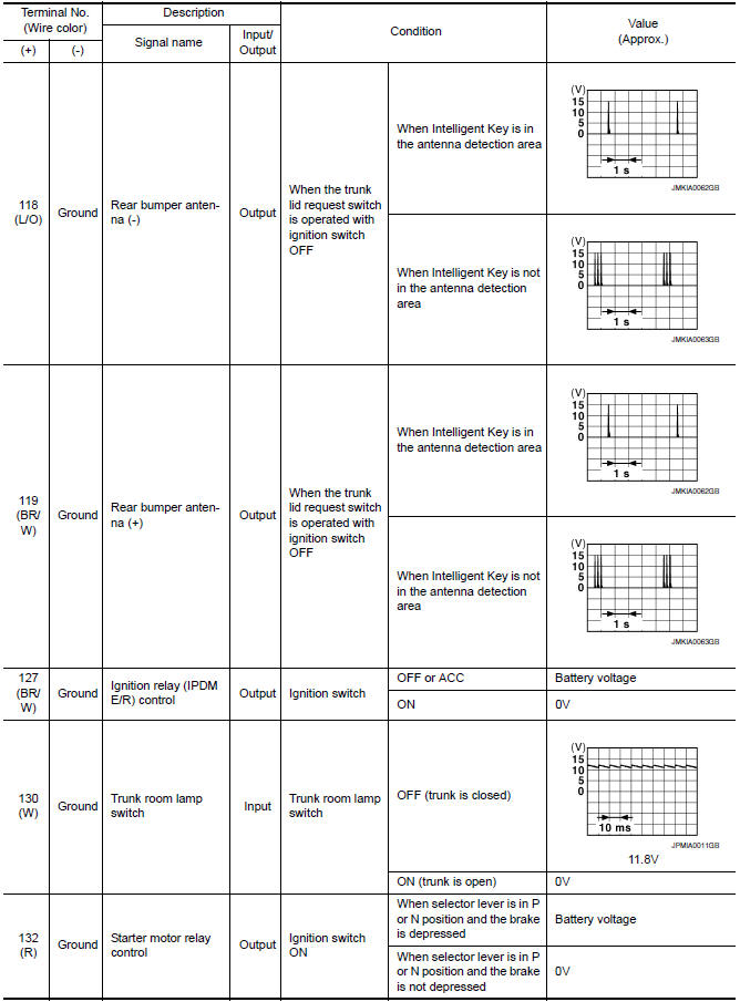
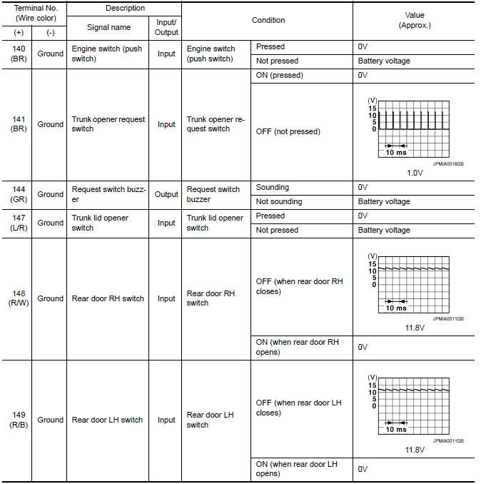
Terminal Layout
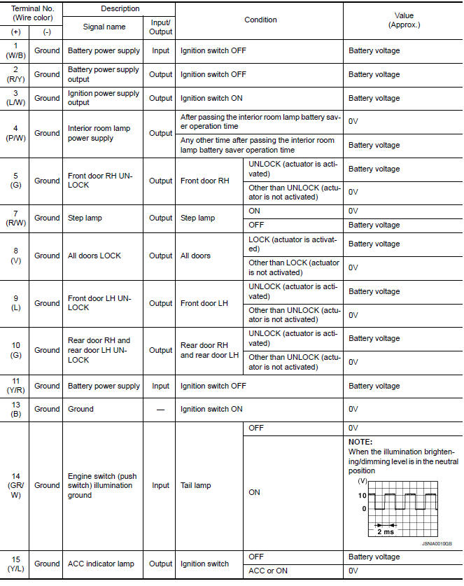
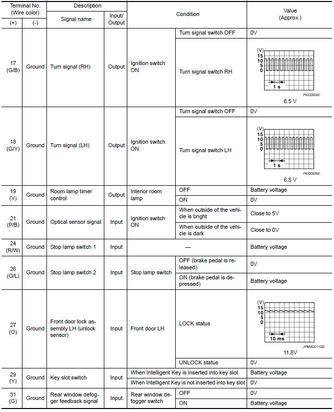
Physical Values
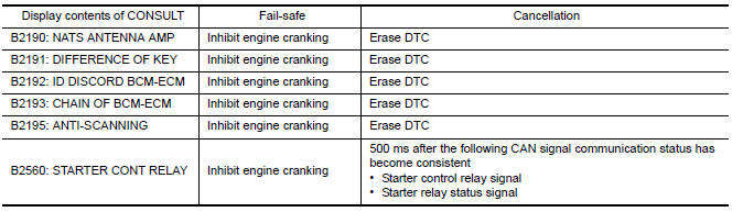
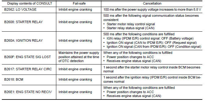
Fail Safe
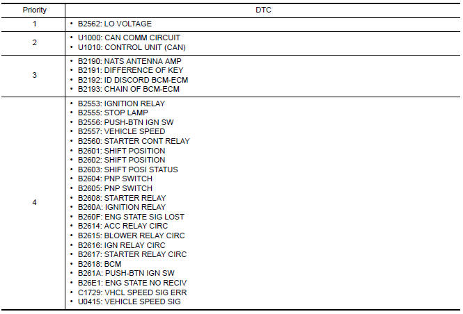
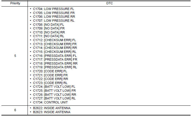
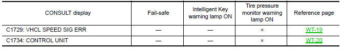
DTC Inspection Priority Chart
If some DTCs are displayed at the same time, perform inspections one by one based on the following priority chart.
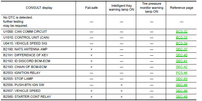
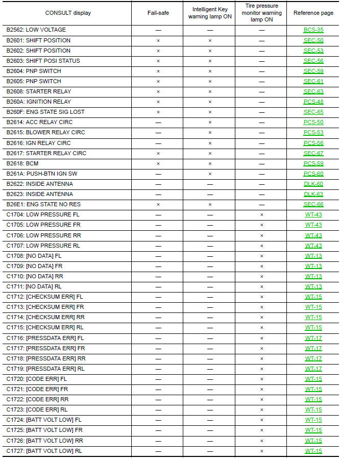
DTC Index
NOTE:
Details of time display
-
CRNT: Displays when there is a malfunction now or after returning to the normal condition until turning ignition switch OFF → ON again.
-
1 - 39: Displayed if any previous malfunction is present when current condition is normal. It increases 1 → 2 → 3...38 → 39 after returning to the normal condition whenever ignition switch OFF → ON. The counter remains at 39 even if the number of cycles exceeds it. It is counted from 1 again when turning ignition switch OFF → ON after returning to the normal condition if the malfunction is detected again.

 IPDM E/R (intelligent power distribution module engine room)
Reference Value
VALUES ON THE DIAGNOSIS TOOL
TERMINAL LAYOUT
PHYSICAL VALUES
Fail Safe
CAN COMMUNICATION CONTROL
When CAN communication with ECM and BCM is impossible,
IPDM E/R ...
Other materials:
Under the hood and vehicle
The maintenance items listed here should be
checked periodically (for example, each time you
check the engine oil or refuel).
Battery*: Check the fluid level in each cell. The
fluid should be at the bottom of the filler opening.
Vehicles operated in high temperatures or under
severe condit ...
Basic inspection
DIAGNOSIS AND REPAIR WORK FLOW
WITH COLOR DISPLAY
WITH COLOR DISPLAY : How to Perform Trouble Diagnosis For Quick And
Accurate Repair
WORK FLOW
1.LISTEN TO CUSTOMER COMPLAINT
Interview the customer to obtain as much information as possible about the
conditions and environment under which th ...
U1200 AV control unit
Description
Replace the AV control unit if this DTC is displayed.
Part name
Description
AV CONTROL UNIT
It is the master unit of the MULTI AV system and it is connected
to each control unit by means of communication. It operates each
syste ...
Nissan Maxima Owners Manual
- Illustrated table of contents
- Safety-Seats, seat belts and supplemental restraint system
- Instruments and controls
- Pre-driving checks and adjustments
- Monitor, climate, audio, phone and voice recognition systems
- Starting and driving
- In case of emergency
- Appearance and care
- Do-it-yourself
- Maintenance and schedules
- Technical and consumer information
Nissan Maxima Service and Repair Manual

0.0059