Nissan Maxima Service and Repair Manual: Refrigerant pressure sensor
Description
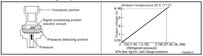
The refrigerant pressure sensor is installed at the condenser of the air conditioner system. The sensor uses an electrostatic volume pressure transducer to convert refrigerant pressure to voltage. The voltage signal is sent to ECM, and ECM controls cooling fan system.
Component Function Check
1.CHECK REFRIGERANT PRESSURE SENSOR FUNCTION
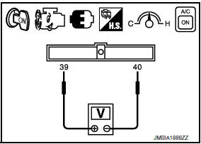
- Start engine and warm it up to normal operating temperature.
- Turn A/C switch and blower fan switch ON.
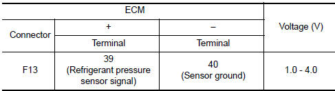
- Check the voltage between ECM harness connector terminals under the following conditions.
Diagnosis Procedure
1.CHECK GROUND CONNECTION
- Turn A/C switch and blower fan switch OFF.
- Stop engine.
- Turn ignition switch OFF.
- Check ground connection E9.
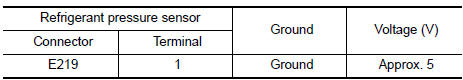
2.CHECK REFRIGERANT PRESSURE SENSOR POWER SUPPLY CIRCUIT
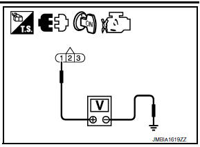
- Disconnect refrigerant pressure sensor harness connector.
- Turn ignition switch ON.
- Check the voltage between refrigerant pressure sensor harness connector and ground.
3.DETECT MALFUNCTIONING PART
Check the following.
- Harness connectors E3, F1
- Junction block connectors E44, E45
- IPDM E/R harness connectors E18, E201
- Harness for open or short between ECM and refrigerant pressure sensor
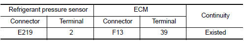
4.CHECK REFRIGERANT PRESSURE SENSOR GROUND CIRCUIT FOR OPEN AND SHORT
- Turn ignition switch OFF.
- Disconnect ECM harness connector.
- Check the continuity between refrigerant pressure sensor harness connector and ECM harness connector.
- Also check harness for short to ground and short to power.
5.DETECT MALFUNCTIONING PART
Check the following.
- Harness connectors E3, F1
- IPDM E/R harness connectors E18, E201
- Harness for open or short between ECM and refrigerant pressure sensor
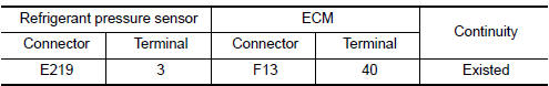
6.CHECK REFRIGERANT PRESSURE SENSOR INPUT SIGNAL CIRCUIT FOR OPEN AND SHORT
- Check the continuity between refrigerant pressure sensor harness connector and ECM harness connector.
- Also check harness for short to ground and short to power.
7.DETECT MALFUNCTIONING PART
Check the following.
- Harness connectors E3, F1
- IPDM E/R harness connectors E18, E201
- Harness for open or short between ECM and refrigerant pressure sensor
8.CHECK INTERMITTENT INCIDENT
 Positive crankcase ventilation
Description
This system returns blow-by gas to the intake manifold.
The positive crankcase ventilation (PCV) valve is provided to conduct crankcase
blow-by gas to the intake
manifold.
D ...
 Variable induction air system
Description
Power Valves 1 and 2
The power valves 1 and 2 are installed in intake manifold collector and used to
control the suction passage of
the variable induction air control system. They a ...
Other materials:
Changing engine oil filter
1. Park the vehicle on a level surface and apply
the parking brake.
2. Turn the engine off.
3. Place a large drain pan under the oil filter B .
4. Remove clips A from the right engine protector
located inside the right wheel well and
then remove protector. Remove oil filter B
with an ...
Headlamp
Wiring Diagram
...
P2118 throttle control motor
Description
The throttle control motor is operated by the ECM and it opens and closes the
throttle valve.
The current opening angle of the throttle valve is detected by the throttle
position sensor. The throttle position
sensor it provides feedback to the ECM, when opens/closes the throttl ...
Nissan Maxima Owners Manual
- Illustrated table of contents
- Safety-Seats, seat belts and supplemental restraint system
- Instruments and controls
- Pre-driving checks and adjustments
- Monitor, climate, audio, phone and voice recognition systems
- Starting and driving
- In case of emergency
- Appearance and care
- Do-it-yourself
- Maintenance and schedules
- Technical and consumer information
Nissan Maxima Service and Repair Manual

0.0076